diy solar

diy solar

EG4 18KPV AC Couple design question (Adding second 18)

millsan1

Solar Enthusiast
Joined
Feb 23, 2023
Messages
452
Location
PA
I've reach ed out to SS Design Team, but figured I would run this by the knowledgeable folks here.

I have an 18 KPV setup as whole home, using supply side feed, with EG4 batteries. All 4 MPPT are populated, and effecticely maxed (not KW, but layout wise) at 12 KW of panels.

I want to add more solar.

The easiest route (I think) is doing AC Couple on the 18.


I have an outbuilding.

What I would like to do is put an AC Panel in the outbuilding, to power items there.

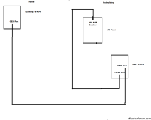
I would then put panels, a second 18 and batteries at the outbuilding. Connect the load from that 18 to the bottom of the AC Panel (like a backfeed setup), and the main from that panel back to the gen port of the current 18, with that 18 set up to AC Couple.

If I need to run generator, it would connect to the 18 in the outbuilding.

In my head, the outbuilding power needs would be fed by the new 18, solar and batteries. Excess would be pushed to the first 18, and then back to grid from there. I have limits set on the current 18 so that I do not push back too much, I assume (dangerous) that those limits are enforced on the unit regardless of where the excess energy comes from (AC Couple or PV).

Does this design work, or did I miss something?


outbuilding.png
 

Attachments

  • outbuilding.png
    outbuilding.png
    46.5 KB · Views: 5
When AC coupled and grid is on, the first 18kpv has no way to limit the output of the AC coupled inverter. Export to grid limits can only be controlled by the first 18kpv by limiting it's DC connected solar production. When the grid is off the GEN connection on the first 18kpv will be turned on and off based on the state of charge of its battery, off when close to fully charged, which will disconnect power to the out building. If you have batteries with the ac coupled 18kpv, you could wire the panel to the load output of the inverter. No matter what you will want to use the GRID connection on the AC coupled inverter for the connection to the GEN port on the first 18kpv, and provide a 90 amp breaker to protect this connection.
 
Just gonna ask since it's not clarified.

Why not just stack the inverters in the main building and run the wires from wherever the new panels are to the main building? Then, connect the sub-panel in your outbuilding to your main building.
 
Just gonna ask since it's not clarified.

Why not just stack the inverters in the main building and run the wires from wherever the new panels are to the main building? Then, connect the sub-panel in your outbuilding to your main building.
Geography of my land. Best use would be to utilize my outbuilding roof. Putting inverter in home would not really work, as there isn't a good place to put the panels.
 
You could run the PV DC circuits from the outbuilding to the house where both inverters would be located.
 
When AC coupled and grid is on, the first 18kpv has no way to limit the output of the AC coupled inverter. Export to grid limits can only be controlled by the first 18kpv by limiting it's DC connected solar production. When the grid is off the GEN connection on the first 18kpv will be turned on and off based on the state of charge of its battery, off when close to fully charged, which will disconnect power to the out building. If you have batteries with the ac coupled 18kpv, you could wire the panel to the load output of the inverter. No matter what you will want to use the GRID connection on the AC coupled inverter for the connection to the GEN port on the first 18kpv, and provide a 90 amp breaker to protect this connection.
I don't understand the bolded portion. When grid is off, 1st KPV will switch the gen port to the load side. If and when it turns off the gen port, the 2nd KPV in the outbuilding will still have batteries and solar for itself.
 
I don't understand the bolded portion. When grid is off, 1st KPV will switch the gen port to the load side. If and when it turns off the gen port, the 2nd KPV in the outbuilding will still have batteries and solar for itself.
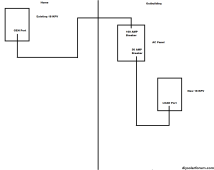
The diagram you posted seems to show that loads will be installed in the breaker panel that is between the 2 inverters, in this configuration when the 1st inverter shuts down it's gen port, the 2nd inverter will sense this and stop providing power on the line/grid port, and the loads on this panel will lose power. If the breaker panel in outbuilding was instead fed by the load connection of the 2nd inverter they would be able to get backup power from the 2 inverter.
 
The diagram you posted seems to show that loads will be installed in the breaker panel that is between the 2 inverters, in this configuration when the 1st inverter shuts down it's gen port, the 2nd inverter will sense this and stop providing power on the line/grid port, and the loads on this panel will lose power. If the breaker panel in outbuilding was instead fed by the load connection of the 2nd inverter they would be able to get backup power from the 2 inverter.
ahhhh! yes, you are right, I hadn't thought of that.
 
OK, I clearly do not understand this well enough, but I believe I now have an idea of how this will work in my situation.

My first misunderstanding is around AC coupling. I assume one would put the Load to the gen on the first KPV. Not right. You put the GRID from the second KPV to the Gen on the first KPV. Load on second KPV would then go to the panel in outbuilding.

I believe I understand how the AC Coupling would work on the 1st KPV. Here is my understanding:

Turn on AC Coupling.
Grid from 2nd KPV connected to GEN on 1st KPV.
Configure Start SOC to like 85%
Configure End SOC to 90%

In that config, if batteries are anywhere below 85%, the AC Coupling would be enabled and the PV power from 2nd KPV would be fed to Grid side of 1st KPV, until batteries reached 90% on 1st KPV. After that, it would phase shift, and no more energy from 2nd KPV would go to 1st, but the 2nd KPV would still be functional, and supply power to its own Load. 2nd KPV would have it's own battery(ies) to provide power to it's own load, and in theory, it could pass that power to 1st, if SOC on 1st is low enough, and the 2nd has enough reserve.

Am I closer to not being an idiot with this design?


outbuilding.png
 
OK, I clearly do not understand this well enough, but I believe I now have an idea of how this will work in my situation.

My first misunderstanding is around AC coupling. I assume one would put the Load to the gen on the first KPV. Not right. You put the GRID from the second KPV to the Gen on the first KPV. Load on second KPV would then go to the panel in outbuilding.

I believe I understand how the AC Coupling would work on the 1st KPV. Here is my understanding:

Turn on AC Coupling.
Grid from 2nd KPV connected to GEN on 1st KPV.
Configure Start SOC to like 85%
Configure End SOC to 90%

In that config, if batteries are anywhere below 85%, the AC Coupling would be enabled and the PV power from 2nd KPV would be fed to Grid side of 1st KPV, until batteries reached 90% on 1st KPV. After that, it would phase shift, and no more energy from 2nd KPV would go to 1st, but the 2nd KPV would still be functional, and supply power to its own Load. 2nd KPV would have it's own battery(ies) to provide power to it's own load, and in theory, it could pass that power to 1st, if SOC on 1st is low enough, and the 2nd has enough reserve.
That is how it will work if off grid or. the grid is off. With the grid connected the 1st 18kpv, will always have the GEN input enabled for AC coupling, regardless of battery state.
 
That is how it will work if off grid or. the grid is off. With the grid connected the 1st 18kpv, will always have the GEN input enabled for AC coupling, regardless of battery state.
Thank you for all your help. Appreciate it
 
That is how it will work if off grid or. the grid is off. With the grid connected the 1st 18kpv, will always have the GEN input enabled for AC coupling, regardless of battery state.
In the above design, when grid is on, according to manual, the Gen port on Inverter 1 is internally connected to the grid on Inverter 1. So in theory, power could flow from gen on inverter 1 to Grid on inverter 2, correct?

For example, let's say load on Inverter 2 is 40 amps, and solar on inverter 2 is generating 20 amps, and batteries are not in the equation, then the required 20 could come from Inverter 1. Right?
yes
 
I am doing something along these lines also . How many amps are you pushing through the GEN port. And are you saying it’s bidirectional current.
 
Last edited:
I think what you need to do is this. Take your incoming grid connection and "Y" it between the "Grid" connections of both inverters. Use some kind of AC power block to make the connections. Then use a fused disconnect at the home to feed the second inverter. When you have a good grid, both systems will export or import power back through their grid connection just like normal.

If you are grid down then you will have two micro grids, one being managed by each inverter. The home inverter would simply use the DC coupled panels. The out building would be programmed to use an AC coupled model. Getting an AC coupled design to work is difficult in the best circumstances. If you wire this in the totally non-standard way this is shown I think it is going to be very difficult to set the software up to work well. You are going to have unexpected interactions going on between the the two inverters that the software programming is not designed to handle. Make sure you get micro inverters that will actually produce power when AC coupled. Enphase had some issues for a long time, but it seems to be working now. Frankly, I would strongly consider just going DC coupled, you already have a second inverter there that has unused MTTP inputs. Why spend more to buy micros?

AC coupled is a pain in the neck to get working.
 
For example, let's say load on Inverter 2 is 40 amps, and solar on inverter 2 is generating 20 amps, and batteries are not in the equation, then the required 20 could come from Inverter 1. Right?
Getting inverters to run in parallel doesn't just happen, they need communication cables to maintain proper phasing and power delivery. I would assume that attempting to run this inverters in parallel with out the proper cables and programming in place won't work.
 
Back
Top