diy solar

diy solar

Feedback on my system design please :)

Aphers

New Member
Joined
Nov 17, 2020
Messages
212
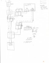
OK be gentle... and I do apologise for the quality of the sketch!
I haven't included cable sizes yet, but I need to measure how long the runs are before I make that decision.
There will actually be two separate sets of PV/MPPT but I've only included one just now, for clarity.
I also haven't included a battery monitor and shunt, but I will need to add that.
The inverter is quite big, too large for the BMS to handle the current directly, so it will be switched using its remote switching port. All the other loads are much smaller, and well within the BMS's capacity.

Any advice gratefully received!
 

Attachments

  • LFP v1.png
    LFP v1.png
    9.5 KB · Views: 31
The + and - is from the PV goes only to the MPPT. Do not mix what happens before and after the MPPT.

Same for the inverter. Keep all the circuits separate, the voltages are not the same before and after the MPPT. There is no "common" ground.

Don't think like a car common ground. It's very different. The "common ground" in a DC is not the same thing as the "ground" of an AC system, do not mix them, they are not the same thing either.


Sometimes just draw it out with a pencil and paper. Don't get wrapped around the axel using a drawing program.
 
Thanks, that sounds like a fairly fundamental error on my part... which is exactly why I'm on here seeking advice ?
Believe it or not I did a few practise sketches on paper before posting that diagram...

Now that you point it out, of course charge controllers don't just sit in line with the positive, I'd have remembered that if I'd switched my brain on.

If anybody has a link to a suitable diagram that I could use for inspiration that would be great. I checked the Resources For Beginners files but couldn't find anything.
 
You will be far better off starting out with what you want to accomplish before you start talking about how the pieces go together. Is this for your garage, an RV, or an off-grid cabin?

You need to go into far more detail than "domestic loads". Is this for lights, a TV, a refrigerator, a whole-house air-conditioner? Each item mentioned goes up roughly a order of magnitude in terms of power needs.
 
This is a system for a yacht.
The "other loads" are the 12v fridge, LED cabin lights, laptop charger and other miscellaneous small loads like a radio, water pump, etc etc. Maybe 30A if you ran them all at the same time.

I'm pretty happy that the main components are all up to the task, it's just a question of wiring it all up now.
 
This makes a lot more sense now that we know what it is for. A common bus on your boat isn't really any different than that of a car.

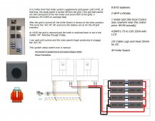
Here are a few drawings I made for myself and my setups. I guess my point would be to not be too detailed in the drawing. When you actually make the thing, do you really need to follow your drawing so close?

img003.jpgScreenshot_20210603-225602_Drive.jpg
 
I guess my point would be to not be too detailed in the drawing. When you actually make the thing, do you really need to follow your drawing so close?

Well I do need to buy the last few components, and due to my location it will be mail order for pretty much everything. So yeah I kind of need to know what breakers, fuses, bus bars, enclosures, etc to buy, and how many of each.

I'll modify my sketch to show the MPPT wired up correctly. I'm not sure I need to change the inverter wiring though? It's a plain inverter, not a charger.
 
Updated to show correct (I hope) MPPT wiring...
 

Attachments

  • LFP v1.1.png
    LFP v1.1.png
    9.5 KB · Views: 13
Looks good to me now.

Have fun. buy more parts than you need now, if you can.

Bigger gauge wire is always better, until it is too heavy for its own good.
 
Thanks. I've got a good length of 10mm2 left over from another project, that should do most of the longer runs (although it's too big for MC4 connectors?). The big worry is obviously hooking up the inverter to the cells, I'm planning the whole layout around the need to minimise that distance, and will use the largest cable which will fit the terminals.
 
Thanks. I've got a good length of 10mm2 left over from another project, that should do most of the longer runs (although it's too big for MC4 connectors?). The big worry is obviously hooking up the inverter to the cells, I'm planning the whole layout around the need to minimise that distance, and will use the largest cable which will fit the terminals.
I bought a Hydraulic crimper for these big wires. The Hydraulic crimper changed everything. I am super glad to have it.

I bought the 16 ton crimper, but I am sure the 10 ton is equally effective.
 

Attachments

  • Screenshot_20210604-074307_Amazon Shopping.jpg
    Screenshot_20210604-074307_Amazon Shopping.jpg
    239.1 KB · Views: 5
Another thought...
Am I doing the right thing wiring the +ve of the MPPT straight to the battery? Or should it go after the fuse? (see attached)
Thanks
 

Attachments

  • LFP v1.12.png
    LFP v1.12.png
    9.7 KB · Views: 9
You have a fuse on the -ve.

If the circuit exceeds the fuse then the circuit is open. It makes no difference if + or - in the circuit.
 
Bumping this with a little update to the system design.
Is this the correct way to wire in the NO-SSR which isolated the inverter? I've put the switch in series with the P- so that when I use that to turn off the inverter, it also cuts off parasitic loads from the relay.

Wiring as far as the +ve bus, and the +ve line from inverter back to battery, will be 70mm2 (485A)
 

Attachments

  • LFP v1.14.png
    LFP v1.14.png
    13 KB · Views: 6
Back
Top