diy solar

diy solar

First Solar System

Zen

New Member
Joined
Sep 21, 2019
Messages
38
Super excited to energize my first solar system, at least the heart of it. I hope you all can help me verify that everything looks right, is safe and make any necessary changes or additions. 100% open to any mistakes or criticisms or if something just looks dumb. I'm new here. :)

Not much is fastened down in case I need to rearrange. To be clear, I'm spending the winter building the rack and array setup to go onto my truck. I'll basically be building the whole project, running/testing appliances, recharging (very few cycles) with AC and wiring/testing the whole system without an array, for now.

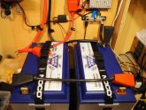
*24V PIP. (2) Battleborn 12V 100Ah.*

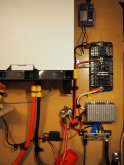
I hope to convert a bunch of appliances via Anderson connectors and Drok converters, so I opted for the split block with the 24V and 12V circuits separate. After any glaring corrections on the general overview, I'll kinda go section by section because I have questions! Battery, main connections area, fuse block and Drok, etc.

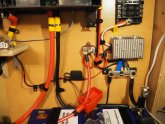
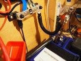
I have decent pictures of each area. Only one negative post with the shunt is connected on batteries.

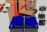
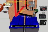
I also made some quick drawings to sort through the mess. Hoping to fire it up this weekend. Any and all help is greatly appreciated! Gratitude to Will for hosting and all who contribute their time here.
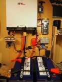
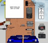
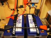
PA040131.JPG Solar Final.jpg PA040133.JPG Battery Wired.jpg PA040134.JPG PA040135.JPG PA040137.JPG

PA040138.JPG
 
Thank you Craig!

That module is the first of the DROK Adjustable step-downs I hope to deploy for converting appliances to DC. I have more to learn before attempting this and need direction on placement in the circuit, with fusing. That's for a bit later.

I have listed questions by area so I'll be back to start with the battery, wiring and connections, and AC line questions.

Here are some components that I used:

DROK Converter


Main DC-DC Converter

https://www.amazon.com/gp/product/B01LY8D7U0/ref=ppx_yo_dt_b_asin_title_o01_s00?ie=UTF8&psc=1

Amp/Volt Meter Hall Sensor


Battery Monitor/Shunt


Split Fuse Block


Battery-to-System Questions:


Battery Wired.jpg PA040133.JPG

-Is it okay that I used 4awg to series connect and 2awg lines to the inverter?

-Does the shunt and connection/wire to the main negative bus look correct?

-Would any fusing or breakers be a good idea, anywhere in this part of the system?

-Where is the best place to install the amp meter to monitor incoming or outgoing power?

AC Questions:

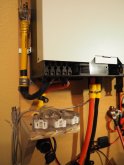
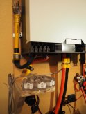
PA040135.JPG AC resized.jpg

-I feel pretty good about the connections and security of these 2 points (AC in & out). The manual suggests 8awg (!) here. I used 12/3 being about the largest I could find and still manipulate on to the board...concerns?

-Grounding: There is a ground screw on the MPP chassis. I have the ground for AC OUT connected here. Should this be the main point for system "grounding"? Should I run a main ground line from this point, eventually to the truck chassis?

-Would any fusing or breakers be a good idea, anywhere in this part of the system?
 
Success! Fired it all up and no actual fires. ?

Immediately beeped my way up to setting 18. No more beeping! ?

Testing AC charging and running my 12V fridge (40W in eco) from the lighter outlet. Correct voltages at all points.

Battery Monitor is showing interesting numbers that I don't really get yet....mainly the in and out resistances.

The manual makes several suggestions for gauging and fusing, as mentioned above but I don't know if these are all applicable due to BattleBorn's protections.

I also altered a couple of Will's recommended settings because I am not using pv inputs (mainly the ones specifying solar or grid priorities).

There's also 2 little spare parts that are not referenced in the manual; one is a ring connector and the other a 1.5" connector plate/fuse. Any idea what these are for?

IMG_20191005_135240 (2).jpg IMG_20191005_135203 (2).jpg
 
AC resized.jpg

-I feel pretty good about the connections and security of these 2 points (AC in & out). The manual suggests 8awg (!) here. I used 12/3 being about the largest I could find and still manipulate on to the board...concerns?
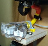
Plugging in and out of these my be a bit troublesome. Might I suggest replacing this with a real outlet box, 2 duplex connectors and Romex 12/3 wire?
 
Plugging in and out of these my be a bit troublesome. Might I suggest replacing this with a real outlet box, 2 duplex connectors and Romex 12/3 wire?
That's right up my alley after 30 years of making AC sparks and arcs! Tested on my soldering station and these yellow jacket cords do have a very positive connection (made for work sites). I plan on permanently securing one for the main inverter-fed appliance line and using the others for quick-plug ins with locking retainers. I appreciate the suggestion and I may do that so I can run romex feeds to remote outlets (double as a junction box).

People talk of solid wiring issues in RVs but I have never seen the issue (for ~AC) if properly installed, secured and breakered up.

Thanks again, something to consider.
 
Maybe this is uninteresting or too simple to have some help here or get yes or no answers. I sure would appreciate it.

-Is it okay that I used 4awg to series connect and 2awg lines to the inverter?

@svetz Thanks for your detailed sticky for the nooblets like me. I couldn't find any info on resistances for series connections or if it matters. Would it be beneficial to run the same gauge here or is this ideal?

-Does the shunt and connection/wire to the main negative bus look correct?

Finally got the monitor to program and I think it is working correctly.

-Would any fusing or breakers be a good idea, anywhere in this part of the system?

Planning on adding one for PV to easily disconnect and cut incoming voltage. Any other places in the system beneficial?

-Where is the best place to install the amp meter (bayite Hall Effect Sensor) to monitor incoming or outgoing power?
 
-Is it okay that I used 4awg to series connect and 2awg lines to the inverter?

The proper gauge to use is a function of maximum current and distance, see What wire gauge should I use?

-Would any fusing or breakers be a good idea, anywhere in this part of the system?
Fuses are safety items. Every wire (not grounding wires) should be fused as close to the power source as possible and so that the current cannot exceed the wire's capacity because every wire could be an accident. For example, in a home the main power goes into the load center; so all of the outlets are on breakers before they go anywhere into the house. This way it'll not only catch a bad device, but someone drilling through the wall. Even small wires are important.

The other thing to consider as you're putting it together is convenience for your maintenance. Handy to have disconnects in key places so you don't have to undo everything.
 
Last edited:
I like a reset breaker 125% of your safe current draw on the positive line from the battery to the PIP, not only prevents too much current being pulled but it can be used as an switch if needed to cut the battery off from the PIP to safely work on it or the panels. I now use an actual battery switch for that, but at first it was handy. In adding a battery shut off switch I kept the circuit breaker in place.
 
Last edited:
Back
Top