diy solar

diy solar

Floating Ground Question on Victron Phoenix 12/500 Inverter in Camper

hotcoldsummer

New Member
Joined
Jun 1, 2023
Messages
24
Location
New Orleans, La
I've read about 10 threads on this but still can't find a really clear answer.

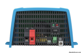
I'm installing a Victron 12/500 inverter in my teardrop and as there's already a neutral-ground bond in the connection between the DC negative bus bar and the chassis, I should leave the inverter set to floating ground and also connect it's ground to the chassis, correct?

Is it ok to ground to chassis by connecting it to the ground bus bar in the AC side of my WFCO power center, as its already grounded to the chassis? This would allow me to avoid drilling another hole in the floor.

Also, if I wanted to install an outlet, I'm assuming I should install a GFCI receptacle as opposed to something like this?
Screenshot 2023-10-29 at 12.14.00 AM.png
 
there's already a neutral-ground bond in the connection between the DC negative bus bar and the chassis
There is?
How is it accomplished?

I should leave the inverter set to floating ground and also connect it's ground to the chassis, correct?
If it already has a N/ G bond. There is no way to leave it floating.
Is it ok to ground to chassis by connecting it to the ground bus bar in the AC side of my WFCO power center, as its already grounded to the chassis?
Yes
Also, if I wanted to install an outlet, I'm assuming I should install a GFCI receptacle
Yes
 
The way my camper was wired at the factory used the chassis as a conductor between the negative battery connection and the WFCO power center. I re-wired it, eliminating this and using larger gauge wire to minimize any resistance issues but I left the wire between the negative bus bar and the trailer frame as a ground. I’ve seen people wire camper vans and rvs with and without a DC ground. Isn’t this the safest option?

My understanding is you should only have one neutral-ground bond in a system. On the AC side for instance, you wouldn’t bond the neutral and ground because there is already a bond af the panel in the campground. However, as I would only use the inverter and battery power off-grid, I left the connection between the trailer frame and negative bus bar.
 
I think that you are confusing N/G bonding with DC negative connection to frame.

In mobile applications, the DC negative is usually connected to the frame of the vehicle.
It's not always required. But Victron equipment usually prefers it.

The N/G bond creates the grounding system.
And there can only be one N/G bond, at any time.
(It's location can change in different operational modes)

Most units that can also receive an outside source (shore power) have a built in N/G relay. Which is switched on in off grid mode. And switched off when passing a grid source through.

This is not the same as using a generator for the alternate source. As they can provide either a bonded or un bonded power supply.

In conclusion.
There are multiple ways to wire a system. Depending on the equipment chosen and options available.
 
' assuming I should install a GFCI receptacle
If you are going to have distributed outlets and cables a GFCI will offer enhanced safety. In this case the Inverter must be AC neutral to earth bounded within the inverter case, as shown in the manual, discussion here,

The Inverter case earth point is always connected the the reference 'earth', DC negative and metalwork/frame.

If you only intend using a single appliance pluged Into the inverter directly, ( no extension cable or multiple outlets), then you have the option of omitting the neutral to earth bond and GFCI. ( unless local regulations require a GFCI)
 
@hotcoldsummer

Read the Grounding Made Simpler papers (a 4 part series), written by Filter Guy. It's in the Resources section of this forum under How To PDF's. I read that (about 4 times!) some years back and was able to confidently proceed with my RV project.
 
Thanks for the responses. Grounding Made Simpler is a great resource. I think I understand now.

I was planning to have a single extension cord outlet but it sounds like not only would a GFCI be needed but also a transfer switch or a ground relay for it to actually work, as it would need a n-g bond only when not connected to shore power? I assumed I would only need additional equipment if I was using the same set of outlets for both shore power and inverter but I guess this is not the case.

I’m a still a bit confused as to why a 1 foot extension cord would require a GFCI it plugging in directly is fine without.
 
Last edited:
If you are going to have distributed outlets and cables a GFCI will offer enhanced safety. In this case the Inverter must be AC neutral to earth bounded within the inverter case, as shown in the manual, discussion here,

The Inverter case earth point is always connected the the reference 'earth', DC negative and metalwork/frame.

If you only intend using a single appliance pluged Into the inverter directly, ( no extension cable or multiple outlets), then you have the option of omitting the neutral to earth bond and GFCI. ( unless local regulations require a GFCI)
Could a simpler solution than using a ground relay or transfer switch be to use a switch like this with sufficient amperage limits to completely disconnect the inverter when it detects AC power?

AC Current Switch Transducer Input 1A-200A Switching Max 0.3A@135V AC/DC Solid Core Self-Powered (16K-SD-NC-AL) https://a.co/d/bjs3V7t

A couple clarifications:

I’m not powering one set of outlets with both shore power and the inverter. I have one AC system with 4 outlets and separately, a single outlet with a 1 foot extension plugged into the inverter with a remote switch to activate the inverter.
 
I’m not powering one set of outlets with both shore power and the inverter. I have one AC system with 4 outlets and separately, a single outlet with a 1 foot extension plugged into the inverter with a remote switch to activate the inverter.
Transfer switch not needed in this situation. Also neutral to protective earth at inverter is only needed if a GFCI is on the inverter output.
With a single outlet on the inverter and a single appliance, the neutral bond and GFCI is optional.
 
Transfer switch not needed in this situation. Also neutral to protective earth at inverter is only needed if a GFCI is on the inverter output.
With a single outlet on the inverter and a single appliance, the neutral bond and GFCI is optional.
Thanks for clarifying! This is what I thought.

So, just to confirm. This is the case even if the inverter doesn't have an internal GFCI?

So I will...
1) Ground inverter chassis to AC ground bar that connects to chassis
2) Leave Inverter internal blade connector set to floating ground
3) Connect single outlet/appliance with a short extension

Side note: There is also a bridge between my DC negative bus bar and the chassis

Thanks again!
 
Back
Top