diy solar

diy solar

Giandel inverter neutral-ground bond in off-grid system

Riverside0396

New Member
Joined
Feb 2, 2023
Messages
5
Location
Earth
Hi,

This is my first ever solar system. Please go easy, I'm here to learn and am eager to receive advice :)

Background threads on the forum I've read:


My system:
- Completely off-grid. No shore power, no utility, no generator.
- True earth ground is connected to DC bus negative, AC breaker ground bus and the inverter/MPPT/solar panel chassis.
- Mission Solar 425W x2 panels
- Victron Smart Solar 100/50 MPPT
- AmpereTime 24V 100Ah LiFePO4
- Giandel PS-3000KAR inverter

Same as mentioned in the other threads, Giandel is advising me that I should NOT create a neutral-ground bond. When I asked them if it's ok to do it after a GFCI device as mentioned in the other threads, they went unresponsive. So I don't have a way to clear ground faults. I am unable to find sub-$600 2kW-3kW discrete inverters for 24V batteries that bond neutral and ground or clearly allow me to.

So this has resulted in a floating neutral circuit and rendered my immense efforts with grounding rods and running 6AWG copper conductors somewhat sadly useless. I have added AFCI/GFCI protected outlet at the point of circuit entry after the breaker. My questions are:

- The polarity tester shows "open ground" and doesn't trip the GFCI outlet when I press the ground fault button. My understanding is that should connect hot and ground, resulting in an imbalance, and trip the outlet. What am I missing?
- Even with the AC circuit breaker off, the voltage detector detects voltage in the circuit. I suspect this is due to the floating neutral? Is that dangerous even if the hot wire is disconnected by the breaker? I am guessing not, but would be good to know.
- How can I truly test a ground fault? Do I have to rely on the "test" button on the AFCI/GFCI outlet?
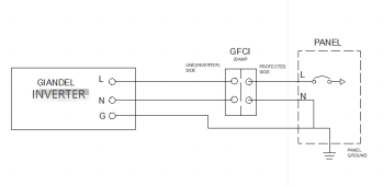
- Lastly, how can I determine if it is safe to bond neutral and ground post a GFCI device like this image? (I'm thinking of getting a 12/3 inline GFCI extension cord and connecting that to the terminal block). What I don't understand is that doing this would result in a ground fault being routed to the neutral at the panel, so the breaker might trip, but doesn't it render the GFCI outlet (after the breaker) useless as it won't detect an imbalance?
ng_bond.png
 
To make the system safe there should be a N-G bond somewhere. Per your diagram, in the panel would be ideal.
Two questions:
1) Why is the DC neg bus connected to earth ground? Is that a Giandel recommendation? Most systems do not use earth ground for either side of the DC system.
2) Why do they recommend against the N-G bond, any explanation?

The reason why the GFCI does not trip with an open ground is because when the button is pushed to make the Hot-Ground connection nothing happens because current does not flow on the ground wire therefore no imbalance is created. That's the whole point of the N-G bond to create a return path back to the source which is the inverter NOT earth ground.
 
1) Why is the DC neg bus connected to earth ground? Is that a Giandel recommendation? Most systems do not use earth ground for either side of the DC system.
The Giandel manual says: "The power inverter is designed to be used with a negative ground electrical system! Don't use with positive ground electrical systems (the majority of modern automobiles, RVs, trucks and boats are negative ground)" -- I read that to mean that the DC negative should be grounded. Am I missing something? Are there downsides to grounding DC negative?

2) Why do they recommend against the N-G bond, any explanation?
They are quite cryptic when I email support. They say: "Since the inverter is not a GFCI type, its neutral and ground are not bonded, so we don't recommend you bond them." So I asked "Can you explain the downside to bonding it? It seems important for safety. Will bonding affect inverter performance or safety? Also if it helps, I am using GFCI/AFCI at all points of circuit start.". They responded saying: "Because this is dangerous, will cause electric shock, also cannot pass HIPOT testing. Unless you use an inverter with a GFCI outlet."

Honestly, If I could find a discrete inverter in 2-3kW range that bonded or clearly allowed to bond N-G, I'd just return this one since I'm still in the return window.

The reason why the GFCI does not trip with an open ground is because when the button is pushed to make the Hot-Ground connection nothing happens because current does not flow on the ground wire therefore no imbalance is created. That's the whole point of the N-G bond to create a return path back to the source which is the inverter NOT earth ground.
To make sure I understand, the tester button does not make current flow because the resistance to ground is high. But, it's lower than the resistance via a human body to ground, so in case of a ground fault, current will prefer to flow through the grounding rods rather than a human body. Correct? Or are the grounding rods completely useless without the N-G bond?
 
@Riverside0396 can you please do the tests I asked for in this post?
 
rendered my immense efforts with grounding rods and running 6AWG copper conductors somewhat sadly useless. I have added AFCI/GFCI protected outlet at the point of circuit entry after the breaker.
Is this a mobile(RV) …
No shore power
… or a building structure?
You probably don’t want or need the dirt/earth ground rods.
The reason why the GFCI does not trip with an open ground is because when the button is pushed to make the Hot-Ground connection nothing happens because current does not flow on the ground wire therefore no imbalance is created.
In a thread I believe I started (re: Giandel floating) it was described to me that GFCI does not require G to operate/function because it senses imbalance H to N. There’s always imbalance to G from H in a properly wired system.
So it may not ‘trip’ with the “test” button perhaps? But it should trip in actual fault? Is that what you are saying?

IIRC when I was running the Giandel my GFCI test button functioned fine, and the GFCI did nuisance trip a couple times.

Am I missing something?
So when I explored this question it took four or five contacts via email with Giandel with diagrams I sent them before I got a diagram confirmation. They said they had to check with an engineer, then replied saying to tie the N-G at the GFCI outlet. Which electrically is the same as bonding at the inverter and I mentioned that; they never responded back.
But the basics you want to know are posts 7 to 10, here.
make sure I understand, the tester button does not make current flow because the resistance to ground is high. But, it's lower than the resistance via a human body to ground, so in case of a ground fault, current will prefer to flow through the grounding rods rather than a human body. Correct? Or are the grounding rods completely useless without the N-G bond?
Are there downsides to grounding DC negative?
Yes. Possible. Oddly, depending on circumstances, “earth/dirt” grounding can solve galvanic corrosion- or cause it. Typically DC is not connected to a driven earth rod into dirt.

With DC ‘ground’ is neg(-). It carries current.

With AC ‘ground’ is bare copper, green clad, or marked sheathed cable to a rod driven into earth(dirt) in one place only, or the ‘potential ground’ usually denoted EGC which is separate from the electrical circuitry ground in the house wiring. AC ground should never have current.

Typical USA house wiring is L1/L2/H/black, N/white, and G/ground/green/bare. G connects to N in one place only - usually the entrance panel- and then connects to a single ground rod driven into the earth/dirt.

One poster on this floating N issue put a fuse inline with a wire and experimentally connected N-G in (I think it was Giandel) his inverter and had no bad consequences.

That was freaking stupid simple and brilliant and I kicked myself for not thinking of that. That’s a good way to test.
I’m going to do that with my Reliable (QZRELB) 2000W psw inverter- just before I bond it on the isolated side of an off/A/B/C/out AC three-pole switch.
I expect it will be fine.

I hope this helps. I hope @John Frum and @timselectric and @Supervstech and the other resident EE-level folks will jump in. @FilterGuy ?
 
@Riverside0396 can you please do the tests I asked for in this post?
@John Frum equipment ground lug is continuous with AC ground (though they did ask in the manual to connect the grounding lug to earth so I have so used the provided 14AWG cable to bond the two — not sure why they’d need that if it’s internally bonded)

AC neutral is NOT continuous with AC ground.
 
@John Frum equipment ground lug is continuous with AC ground (though they did ask in the manual to connect the grounding lug to earth so I have so used the provided 14AWG cable to bond the two — not sure why they’d need that if it’s internally bonded)

AC neutral is NOT continuous with AC ground.
I guess to keep the sparks to a minimum you should check for continuity between ac.hot and ac.ground.
 
Is this a mobile(RV) …… or a building structure?
You probably don’t want or need the dirt/earth ground rods.

In a thread I believe I started (re: Giandel floating) it was described to me that GFCI does not require G to operate/function because it senses imbalance H to N. There’s always imbalance to G from H in a properly wired system.
So it may not ‘trip’ with the “test” button perhaps? But it should trip in actual fault? Is that what you are saying?

IIRC when I was running the Giandel my GFCI test button functioned fine, and the GFCI did nuisance trip a couple times.


So when I explored this question it took four or five contacts via email with Giandel with diagrams I sent them before I got a diagram confirmation. They said they had to check with an engineer, then replied saying to tie the N-G at the GFCI outlet. Which electrically is the same as bonding at the inverter and I mentioned that; they never responded back.
But the basics you want to know are posts 7 to 10, here.


Yes. Possible. Oddly, depending on circumstances, “earth/dirt” grounding can solve galvanic corrosion- or cause it. Typically DC is not connected to a driven earth rod into dirt.

With DC ‘ground’ is neg(-). It carries current.

With AC ‘ground’ is bare copper, green clad, or marked sheathed cable to a rod driven into earth(dirt) in one place only, or the ‘potential ground’ usually denoted EGC which is separate from the electrical circuitry ground in the house wiring. AC ground should never have current.

Typical USA house wiring is L1/L2/H/black, N/white, and G/ground/green/bare. G connects to N in one place only - usually the entrance panel- and then connects to a single ground rod driven into the earth/dirt.

One poster on this floating N issue put a fuse inline with a wire and experimentally connected N-G in (I think it was Giandel) his inverter and had no bad consequences.

That was freaking stupid simple and brilliant and I kicked myself for not thinking of that. That’s a good way to test.
I’m going to do that with my Reliable (QZRELB) 2000W psw inverter- just before I bond it on the isolated side of an off/A/B/C/out AC three-pole switch.
I expect it will be fine.


I hope this helps. I hope @John Frum and @timselectric and @Supervstech and the other resident EE-level folks will jump in. @FilterGuy ?
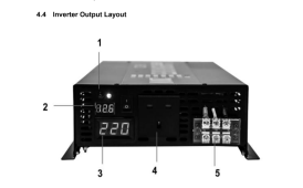
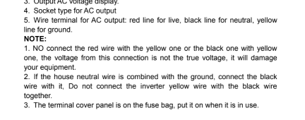
Is this the Reliable inverter you have? See the notes in the manual.
You can try using 5W night light lamp between N and G to see if it will light up the lamp or not, the lamp my barely light up so I would use AC Amp meter to see how much current is flowing.
1675459780395.png

1675459845877.png
 

Attachments

  • ReliablePower Pure_Sine_Wave_Inverter_Manual.pdf
    331.5 KB · Views: 6
Last edited:
My post is for 12VInsrall since he said:
'That was freaking stupid simple and brilliant and I kicked myself for not thinking of that. That’s a good way to test.
I’m going to do that with my Reliable (QZRELB) 2000W psw inverter- just before I bond it on the isolated side of an off/A/B/C/out AC three-pole switch.
I expect it will be fine.'


I hate to see he damages his Inverter.
The Yellow wire is Ground and it is also connected to the chassis.
The Red Line, Black is Neutral.
The color code they are using is screwy.
 
Is this the Reliable inverter you have? See the notes in the manual.
You can try using 5W night light lamp between N and G to see if it will light up the lamp or not.
Don’t have the manual- wasn’t included.
I’ll download it somewhere.

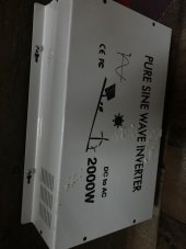
But no, it’s the similar but different white one.

image.jpg
Its the Giandel.
Do you understand that note?
I sure don't.
From the OP- he has a Giandel. I do as well but interjected the ‘test’ idea.
This note?
:) I can’t tell if you’re serious but I did the test. AC hot is NOT continuous with AC ground.

Knowing this, what do you think?
i interpreted it as “no continuity” if that’s what you meant.
 
@Riverside0396

If it were me...

This simplest thing to do for the dc domain is leave it floating.
For 24 volt systems that is acceptable.

For the ac domain...
Before I connected the inverter to the ac distribution panel I would test the inverter output voltage.
Hot to neutral should be 120VAC
Hot to ground should be ~0VAC.
neutral to ground should be ~0VAC

I would modify your diagram to move GFCI onto one or more branch circuits.
Then I would test the system.
With the inverter connected to the ac distribution panel.

Test 0:
expected results:
Hot to neutral should be 120VAC
Hot to ground should be 120VAC.
neutral to ground should be 0VAC

Test 1: make a ground fault on a non-gfci protected branch circuit.
expected result: breaker should trip/or inverter should shut down to clear the fault.

Test 2: make a ground fault on a gfci protected branch circuit.
Expected result: breaker should trip/or inverter should shut down to clear the fault.

Test 3: run a small load on a gfci protected branch circuit.
Expected result: system should run normally.

If I'm wrong about anything, hopefully one of the electricians or electrical engineers correct my errors.
UPDATED: fixed a thinko in one of my tests.
 
Last edited:
hate to see he damages his Inverter.
Not as much as me.
But I’ll meter it up and figure it out, maybe try the bulb.

Or dig out my hex crimpers and some cable and connect the thing to 12V, and pardon me, but have you seen where I put my Klein clamp meter?
 
Test 0:
expected results:
Hot to neutral should be 120VAC
Hot to ground should be 0VAC.
neutral to ground should be 0VAC
He might see 55-60VAC with essentially no amps N-G and H-G on the Giandel.
That’s what two i tested did. Hedges or RCinFla comforted me on that; either an inductive voltage or a sine conversion effect.
 
He might see 55-60VAC with essentially no amps N-G and H-G on the Giandel.
That’s what two i tested did. Hedges or RCinFla comforted me on that; either an inductive voltage or a sine conversion effect.
N and G are bonded at the distribution panel so I would expect N-G to be 0 volts and H-G to be 120 volts.

I updated my tests to fix a thinko.
 
Last edited:
Reporting back on what I learnt to close out the thread with information for future readers.

Here's what I changed:
- I decided to turn some of the electronic loads to be 12v DC loads, reducing minimum inverter capacity and increasing efficiency. I still need to find a reasonable 600W 24v to 12v DC step-down converter. Suggestions?
- I am returning the Giandel 3kw inverter (I was putting it behind a 15amp breaker and using it as a 1800w inverter anyway; did this because Giandel 2kw didn't have a terminal block)
- I have bought a Victron Pheonix 24v/1200VA inverter which has a configurable jumper for neutral-ground bonding even though it ships as floating neutral.
- There's no terminal block on the Pheonix so I will be mounting a junction box to connect to the romex.

Here's what I learned and will carry forward to other projects:
As a newbie DIYer, it's ok for me to rely on passive (panels, batteries, ...) components designed in China, etc. so long as I use appropriate fuses and breakers. For the active components (MPPT, inverter, ...) , I need to budget for components designed and more importantly, supported by reputable companies that provide high-quality documentation in language I can understand. Giandel was disappointing in the way they communicated over email and the manual is badly written. And if they're cutting corners on things customers interface with directly, ...

Thanks to everyone on this thread that chimed in. I appreciate your help and valuable time.
 
Last edited:
The Victron Pheonix 24v/1200VA is built like a tank with heavy Torroid transformer and it can handle surge really well, plus it is made so you can have N-G bonding as needed. I have two of 12V/1200VA/1000W old version without V.E.
 
Ok it's about not making a human the circuit for leathal current to flow. So connecting one side of the voltage to conductor that the human is connected too ie earth or metal work etc. While there is a risk that the human can come in contact and complete the circuit .
 
Ok it's about not making a human the circuit for leathal current to flow. So connecting one side of the voltage to conductor that the human is connected too ie earth or metal work etc. While there is a risk that the human can come in contact and complete the circuit .?
 
Back
Top