diy solar

diy solar

Ground mount ground question

Subdood

Photon Wrangler
Joined
Mar 27, 2022
Messages
564
Location
NE Kentucky
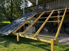
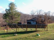
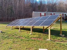
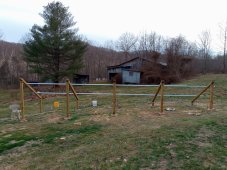
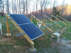
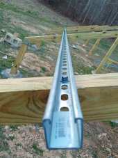
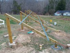
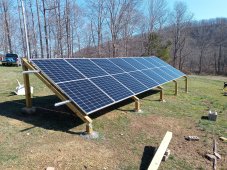
Hey all, I just finished building a ground mount array with 8 445W bifacials. I used wood for the support structure and unistruts to place the panels on. The struts are galvanized steel and are joined together with a splint plate. There are 3 10ft unistruts joined by the splints, placed in parallel about 45in apart to accommodate the panels.

I took a meter and checked to see if the rails have conductivity by measuring the resistance and they show 0 ohms resistance. I'm assuming the panel frames are anodized aluminum with means they are not conductive. I was planning on joining the panel frames together with some kind of weeb type clamp and copper wire. Plus I would attach the clamps and wire to each rail. BTW, the panels' Isc rating is about 15A at max bifacial power (about 575W) which is unlikely to be reached.

Okay so my questions are these-

1) What gauge wire do I need to use to tie the frames and rails together? I have read it should be 6 gauge, but that 10 gauge is acceptable. I'm guessing it doesn't matter if it's insulated wire like THWN or bare wire? I do plan on stripping away the insulation where it meets the ground clamps. The PV wires and ground wire will meet at a junction box at the array.

2) From the junction box at the array, I am running the PV + and - wires (THWN), which will be 10ga thru conduit (buried 18 inches) about 50ft back to the inverter PV input. The inverter will be mounted in a closet in our house. I was also planning on running the frame ground wire in the conduit. Since this wire will be conduit, does it need to be wire rated for conduit, like THWN, or is bare wire okay? And if I use 6ga ground wire on the frames, does it also need to be 6ga in the conduit?

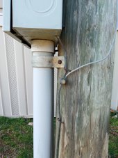
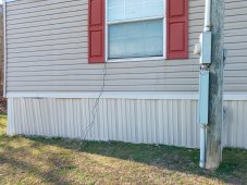
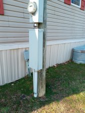
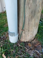
3) I would like the ground wire to go to the service pole ground rod, which is about 15ft from where the conduit will enter the house. I don't want to run this ground wire back to the inverter in case of lightning strikes. So the question is how do I get this wire to the ground rod if it's in conduit? Could I have like a Y or T junction where the conduit comes up out of the ground at the house where I run the ground in its own conduit to the ground rod?

Sorry for the lengthy question, but I want to make sure I'm doing this right and safely. Thanks. I am enclosing some pics of what the ground mount looked like before and after we put on the panels.
 

Attachments

  • 20230223_163157.jpg
    20230223_163157.jpg
    1 MB · Views: 103
  • 20230223_163113.jpg
    20230223_163113.jpg
    1.2 MB · Views: 96
  • 20230215_174047.jpg
    20230215_174047.jpg
    412 KB · Views: 95
  • 20230218_173941.jpg
    20230218_173941.jpg
    577.8 KB · Views: 88
  • 20230213_174248.jpg
    20230213_174248.jpg
    253.7 KB · Views: 92
  • 20230214_133622.jpg
    20230214_133622.jpg
    587.6 KB · Views: 88
  • 20230221_105649.jpg
    20230221_105649.jpg
    700.3 KB · Views: 92
Last edited:
I did the same thing. The panels ground point on the underside of the frame are daisy chained together with a single ground wire going the the same ground point as where the inverter and surge suppressor tie to the house ground. My main service panel, sub panel, the Growatt, and solar panels are all at the same ground potential.
 

Attachments

  • B405A88B-4318-46D1-AC9E-FF323BFAC08B.jpeg
    B405A88B-4318-46D1-AC9E-FF323BFAC08B.jpeg
    894.1 KB · Views: 53
I did the same thing. The panels ground point on the underside of the frame are daisy chained together with a single ground wire going the the same ground point as where the inverter and surge suppressor tie to the house ground. My main service panel, sub panel, the Growatt, and solar panels are all at the same ground potential.
Thanks. That's what I want to do. What items did you use to tie the panels together?

But, I was wondering if you or anyone else like @FilterGuy, @timselectric, @Hedges, etc, can answer my particular questions? I know grounding is a much debated topic on here, but I just want to be sure I'm doing this right, and safely.

I've been doing some basic capability testing the last few days to see what it can handle power wise. I have 3.6kW of panels going to an EG4 6500 inverter. I'm going to do a bit more testing before I start running wires, laying conduit, etc. What are the particulars on your system and has it been running a while?
 
The daisy chaining like @Brett V describes is one of the two styles of PV frame grounding. One thing to keep in mind is that the NEC requires the ability to remove one panel without disrupting the grounding of all the other panels. Furthermore, the wire is required to be one continuous wire. (If you have to splice the wire, it must be spliced with a crimp connector or some other irreversible connection method.)

The second common method is to use WEEB washers and ground just the mounting Rack. Weeb washers are special washers that have teeth or barbs that will cut through the aluminum oxide of the frame and or mount in order to ensure there is a good electrical connection. WEEB washers are also used between the various components of the racking system so everything is bonded together. Then you just have to bond a wire at one point of the rack and tie that back to the common ground point of the rest of the system.

More can be found in this resource:

Thanks. I just read your panel grounding post. So, my highest bifacial Isc is 15A, so 1.56 of that is about 23A. So based on that then, I'm guessing I can use a bare 10ga wire to connect my frames together? Solid or stranded or does it matter?

This wire will come into the junction box along with the two PV wires. Can I transition this bare wire to a 10ga THWN wire that goes into the conduit? You mentioned that it has to be one continuous wire, but does mean only between the panel frames and rails, or does it have to be the same conductor from frames to the pole ground rod? Also, is okay where the conduit comes up out of the ground at the house to run a split conduit so that the ground wire can go its own way to the grounding rod?

I just went outside and got some pics of the service panel that feeds the house. I don't see a grounding rod, maybe it's buried. But I do see a visible copper wire going from the panel down into the ground. Is it okay just to attach the array ground wire to this wire?
 

Attachments

  • 20230225_151552.jpg
    20230225_151552.jpg
    194.3 KB · Views: 24
  • 20230225_151516.jpg
    20230225_151516.jpg
    376.2 KB · Views: 24
  • 20230225_151505.jpg
    20230225_151505.jpg
    230.6 KB · Views: 24
  • 20230225_151456.jpg
    20230225_151456.jpg
    279.8 KB · Views: 26
Last edited:
The array ground wire can be attached to any point of the existing grounding system. At which point it becomes part of the grounding system.
#6 minimum at the array for any part that isn't protected by conduit. Otherwise size (equipment grounding conductor) correctly for the largest solar circuit conductors.
 
#6 minimum at the array for any part that isn't protected by conduit. Otherwise size (equipment grounding conductor) correctly for the largest solar circuit conductors.
So, to verify, you're saying it can transition from bare 6ga at the junction box to 10ga THWN into the conduit? Sorry if I'm nitpicking, I just to make sure I understand. You guys are very helpful, so thank you.
 
I used unistrut for the rails on one of my arrays and there was continuity between the rails and panel frames. I used solar clamps to attach the panels to the unistrut though. If you used something else then there probably isn't a good enough connection.
 
So, to verify, you're saying it can transition from bare 6ga at the junction box to 10ga THWN into the conduit? Sorry if I'm nitpicking, I just to make sure I understand. You guys are very helpful, so thank you.
Correct
 
One thing to keep in mind is that the NEC requires the ability to remove one panel without disrupting the grounding of all the other panels. Furthermore, the wire is required to be one continuous wire. (If you have to splice the wire, it must be spliced with a crimp connector or some other irreversible connection method.)
I believe you are mixing the NEC requirements for a GEC (grounding electrode conductor) and an EGC (equipment grounding conductor). What the OP describes is an EGC because he's carrying the ground back to the service main ground system (at least as I read it). An EGC can be spliced as many times as you need to, there's no requirement for irreversible crimps or continuous wire. For the GEC you are correct, it must either be a continuous conductor or irreversibly spliced.
 
I used unistrut for the rails on one of my arrays and there was continuity between the rails and panel frames. I used solar clamps to attach the panels to the unistrut though. If you used something else then there probably isn't a good enough connection.
I also checked to see if there was continuity between the 3 spliced unistruts and there was. I haven't checked to see if the panel frames are conductive or not, but I'm guessing not. So, it looks like I'll need 10 ground clamps, one for each panel and two for each unistrut, tied together with a bare 6ga wire.
 
I also checked to see if there was continuity between the 3 spliced unistruts and there was. I haven't checked to see if the panel frames are conductive or not, but I'm guessing not. So, it looks like I'll need 10 ground clamps, one for each panel and two for each unistrut, tied together with a bare 6ga wire.
They are, just not the anodized exterior
 
They are, just not the anodized exterior
Are they Anodized? I did not think so..... but the aluminum frames do Oxidize and Aluminum Oxide is nonconductive. That is why the grounding clamps must be designed to cut through the oxidized layer and make contact to the aluminum below.
 
Are they Anodized? I did not think so..... but the aluminum frames do Oxidize and Aluminum Oxide is nonconductive. That is why the grounding clamps must be designed to cut through the oxidized layer and make contact to the aluminum below.
I thought panel frames were always anodized
 
Back
Top