diy solar

diy solar

help with "large capacity" cell testing and charging

sstephan

New Member
Joined
Apr 22, 2024
Messages
7
Location
israel
hello guys (newb alert)
i bought some "grade a 105ah" lfp cells from aliexpress and want to do capacity verification / match before i assemble them into a pack .
The problem is , i never fully charged / tested large capacity cells .
I just hooked up one of the cells to my isdt charger , set the charge current to 15a and it seems that it wont stop the charge for very long time .
I don't know what is the cut off current for my charger , i guess its more suited for smaller batteries and probably waiting for the current to drop to 100ma or so .
As i understand , normally the cutoff current should be around 5% , so i should stop charging once the current drops below 5a , correct?
should i leave it "float charging" at this current for some time , or immediately stop ?

I never had issues with smaller capacity cells (8-16ah) , the charger would stop the charge automatically once it goes into cv mode and the current drops below certain value .
 
3.65V @ 0.05C, so 5.25A (5 is close enough)

Do not float charge. That's the opposite of stopping a charge.

Many RC chargers cut off charge at 10% of start current. Yours may vary.

Cells are supposed to ship at 30% SoC or lower due to hazmat requirements. Most seem to be between 30-50% in reality.

You may need 70Ah/15A = 4.7h of 15A charging + absorption for each cell. Cell voltage can seem like it's never going anywhere or only going up very slowly. This is normal. There's an abrupt increase at the end. 3.5V to 3.65V will go VERY quickly.

If your test leads are thin, you may see excessive voltage drop. Compare charger reported voltage to voltage measured at the terminal. The terminal voltage is what matters.
 
i have a power supply i can use to charge up to 48Ac , but no cut off current adjustment .

also what is the best way to test capacity - constant current , constant power or simple resistive load?
 
i have a power supply i can use to charge up to 48Ac , but no cut off current adjustment .

also what is the best way to test capacity - constant current , constant power or simple resistive load?

Constant current is the most sensible as you can equate current * time to get Ah. If the discharger reports Ah, Wh, etc., it doesn't matter.

If a cell datasheet specifies a specific test method, that's preferred.
 
I got 94.6ah out of the first cell. Don't know if its good or bad for aliexpress quality.
I discharged with 20a cc 2.5v cut off. I guess with lower discharge it could be a bit more.
 
I got 94.6ah out of the first cell. Don't know if its good or bad for aliexpress quality.
I discharged with 20a cc 2.5v cut off. I guess with lower discharge it could be a bit more.

If your charger determined 2.5V cut off with the test leads, then the OCV of the cell may have been higher, so there might have been a little more to give.

These cells are typically rated for 0.5C or 1.0C capacity, so 20A should yield rated capacity or better.

I'd say the results are decent for an unproven Aliexpress source. If this is a reputable supplier, the results are concerning. It would also be good for you to verify your charger is measuring current accurately. Verify with a clamp DC ammeter.

RC chargers aren't necessarily very accurate. I have a $400 iCharger 4010 duo. Two channels at 40A each, and both channels can be run on the same battery in synchronous mode for 70A total. Even with pretty beefy dual 8awg test leads, there was a notable difference between open circuit voltage and test lead voltage. I got around this by using leads to the balance port to use the open circuit votlage.

There are some charts starting on page 2:

 
RC chargers aren't necessarily very accurate. I have a $400 iCharger 4010 duo. Two channels at 40A each, and both channels can be run on the same battery in synchronous mode for 70A total. Even with pretty beefy dual 8awg test leads, there was a notable difference between open circuit voltage and test lead voltage. I got around this by using leads to the balance port to use the open circuit votlage.
i used electronic load for discharge with 4 leads , so the voltage measurement is directly from the cell and not influenced by current draw .
second cell tested at 104.2ah
i bought them from litokala aliexpress . those are probably rebranded eve cells , don't know exactly what's "wrong" with them .
definitely much cheaper then buying new cells from alibaba . i don't care if they will be 85ah instead of 105ah , as long as nothing will explode or other issues .
 
I think your cells are going to be fine If they test over or very close to rated capacity at 0.2c (20A in your case).

What voltage pack are you building and for what loads? For me the ability to run small cells like 100ah at 1C is very important so I also test voltage drop under 1C load (DC internal resistance).

The easiest way to check a pack is with an inverter and a heater. I always do it at 50% or less state of charge to discover the worst behavior of the pack. Record voltage, start a 1c load (a heater) and record instatenous voltage drop. Divide by amps. That's your ohmic DC internal resistance. Keep it on for 2~3 minutes for the voltage drop to stabilise. Record where it stabilises. Switch the heater off and recover how far it recovers. Divide by amps and subtract ohmic resistance. This is your DC polarisation resistance.

I've encountered old, most likely unused, cells that measured good capacity and good AC IR (this is closely related to ohmic resistance) but these cells had horrible polarisation resistance. To the point I wouldn't want them for free.

Of course if your cells have laser etched qr codes you can simply check manufacturing dates without all this. There is an app called lifepo qr code scanner for it.

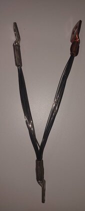
However I like this stuff so I've built myself a simple shunt for the purpose of testing individual cells. I can quickly load a single cell with 50/84/100/170A. If you have copper crimp terminals for 8mm2/AWG8 wire and Kanthal A1 22gauge heating wire. You can put 10 in parallel in this arrangement.(measure the right resistance of course)
20240425_130144.jpg
And you gave a multipurpose shunt. I use two sets of pliers to apply it(it gets hot quick) . And not to battery terminals, but a piece of busbar cut in half. I use an oscilloscope to check cells quickly, but there is no reason a precision volt meter couldnt be used.

It can also be used on the lowest setting to "balance" cells with too high voltage.

Oh, and post pictures of your cells if they are not well documented yet.
 
What voltage pack are you building and for what loads? For me the ability to run small cells like 100ah at 1C is very important so I also test voltage drop under 1C load (DC internal resistance).
currently the plan is to make 16s / 48V pack . at first stage i plan to put few panels on a pergola , 60a mppt charger and 3kw inverter .
i'm also building my own diy 2 stage inverter (48v -400v dc , then 400v dc to 240ac) .
if all goes well i'll probably add more batteries and solar panels on the roof .
 
Back
Top