diy solar

diy solar

Help with math calc

andy_acacia

New Member
Joined
Mar 14, 2022
Messages
11
I would like some help with calculating theoretical voltage and current please.

What is the max ( theoretical) voltage and amperage I will get from the following array where each panel max is 10a 40v

2 panels in series + 2 panels in series = ?a ?v

I understand 4 in series would be 10a 160v. Likewise 4 in parallel would be 40a 40v.

These panels will charge a 24v battery bank using a 100v 40a MPPT.
Two panels in series = 80v @ 10a
+
Two panels in series = 80v @ 10a

= 80v @ 20a
Somebody please check this ?
 
So the common way many people here would refer to that wiring is 2s2p...

At face value it looks like Voc 80v, and Isc 20a.

But in reality, the Voc depends on temperature, so you need to also calculate in the corrected Voc value using the 'Temperature Coefficient of Voc' spec on the panels, to get a more accurate idea of what the Voc will actually be at the lowest possible operating temperature (since Voc goes up as temperature goes down).

More info here (and calculator):
 
I would like some help with calculating theoretical voltage and current please.

What is the max ( theoretical) voltage and amperage I will get from the following array where each panel max is 10a 40v

2 panels in series + 2 panels in series = ?a ?v

I understand 4 in series would be 10a 160v. Likewise 4 in parallel would be 40a 40v.

These panels will charge a 24v battery bank using a 100v 40a MPPT.
So if my maths is correct... your mppt is well able to handle 4 panels in the configuration you suggested.. please wait till somebody confirms my maths please...
 
from the following array where each panel max is 10a 40v
Using the word "max" implies using Voc and Isc of the panels. Are you looking to calculate expected working values (with Vmp and Imp)?

Since you have 4x 400W panels, thats a 1600W array.
All the answers to your underlying question should result in V x A = 1600W

4S: 160V x 10A = 1600W
4P: 40V x 40A = 1600W
2S2P: 80V x 20A = 1600W

Whether this works with your 100V SCC depends on the actual Voc value of your panels and the temp adjusted Voc based on your expected low temps (voltage rises as temperature drops below 25C/77F).
 
So the common way many people here would refer to that wiring is 2s2p...

At face value it looks like Voc 80v, and Isc 20a.

But in reality, the Voc depends on temperature, so you need to also calculate in the corrected Voc value with the 'Temperature Coefficient of Voc' spec on the panels, to get a more accurate idea of what the Voc will actually be at the lowest possible operating temperature (since Voc goes up as temperature goes down).

More info here (and calculator):
Thank you Samsonite for confirming the same answer as Culchee ?

I had assumed the 2s2p and 4s2p acronym I'd seen in the forms was as you've now confirmed to me, so great to learn something new.
 
So if my maths is correct... your mppt is well able to handle 4 panels in the configuration you suggested.. please wait till somebody confirms my maths please...

Would also have to know what the specs are on the charge controller in order to be able to determine what wiring he would want to optimally run with.

EDIT:
Meaning we know the Max PV Voltage is 100v, it's also nice to know if they publish a spec for MPPT startup voltage, or ideal MPPT operating voltage range, and max amps, this can also help to factor in when finding the best wiring topology.
 
Last edited:
Using the word "max" implies using Voc and Isc of the panels. Are you looking to calculate expected working values (with Vmp and Imp)?

Since you have 4x 400W panels, thats a 1600W array.
All the answers to your underlying question should result in V x A = 1600W

4S: 160V x 10A = 1600W
4P: 40V x 40A = 1600W
2S2P: 80V x 20A = 1600W

Whether this works with your 100V SCC depends on the actual Voc value of your panels and the temp adjusted Voc based on your expected low temps (voltage rises as temperature drops below 25C/77F).
Thank you for a very clear answer. Much appreciated.

I realise this is now a different question but what would be better at maintaining the battery bank, a parallel or 2s2p set up?

I'm in the UK and it's very often overcast, as it is today. I've tested each panel before determining which way to connect them.
Each panel was near to the expected 40v but amperage was <1a. Feels like it'll take ages to charge up the 24v 200ah battery bank with such low amps being produced from the panels.
 
Last edited:
Thank you for a very clear answer. Much appreciated.

I realise this is now a different question but what would be better at maintaining the battery bank, a parallel or 2s2p set up?

I'm in the UK and it's very often overcast, as it is today. I've tested each panel before determining which way to connect them.
Each panel was near to the expected 40v but amperage was <1a. Feels like it'll take ages to charge up the battery bank with such low amps.


Under what condition were you measuring that <1a, and where?

It would be helpful to know the actual specs on the charge controller. The charge controller will load down the solar panel circuit, which pulls down the voltage, as the amps starts to rise. But the solar side voltage must stay some amount higher than battery voltage in order to charge.

Some chargers, like Victron for example actually say that solar circuit voltage must be 5v higher than battery voltage in order to charge.

What is your Vmp and Imp spec on your panels? You may want to measure the actual volts and amps on the solar circuit while the battery should be charging in bulk cycle.

Keep in mind that the solar circuit will only be pulling full power while the battery charger side is on bulk phase (while in CC or constant current stage), once the charger flips to absorption phase (CV or constant voltage stage), the solar circuit will start to relax, amps will taper off, as the power demand is at a value less than max amps rating (on battery side) of the charger, so the demand on the input side tapers down, solar volts starts to rise again as solar amps drops.
I tested each panel with my multimeter, unconnected to anything else and pointed South at about a 45deg angle. Conditions were overcast but not dark.
<1a feels really poor
 
I tested each panel with my multimeter, unconnected to anything else and pointed South at about a 45deg angle. Conditions were overcast but not dark.
<1a feels really poor

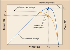
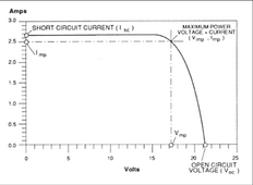
Yeah, so unconnected is open-circuit state, the panel will show the highest voltage and the lowest (no) current. A short circuited panel will show the highest current and the lowest voltage.

You would most conveniently need a solar panel tester, which can actually load down the panel to the operating resistance value at Imp (amps @ maximum power) in order to see how many amps the panel would be flowing.

Solar Panel Tester:


Can also get a rough estimate by looking up the power curve chart for your panel.

1704064147220.png

1704064291084.png

Or can also get an amp clamp (probe/meter), and actually hook up all your panels with your MPPT charge controller to a low battery bank, so it is charging bulk stage (max battery amps), and then check the amps and volts on a single panel (in the wired string), or read on total circuit to confirm.
 
Last edited:
Back
Top