


GSXR1000
Solar Enthusiast
- Joined
- Nov 20, 2020
- Messages
- 865
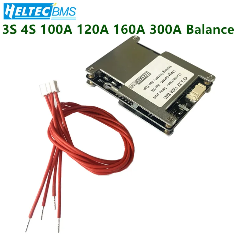
i am looking for a high current BMS. Any thoughts of these.
 www.aliexpress.com
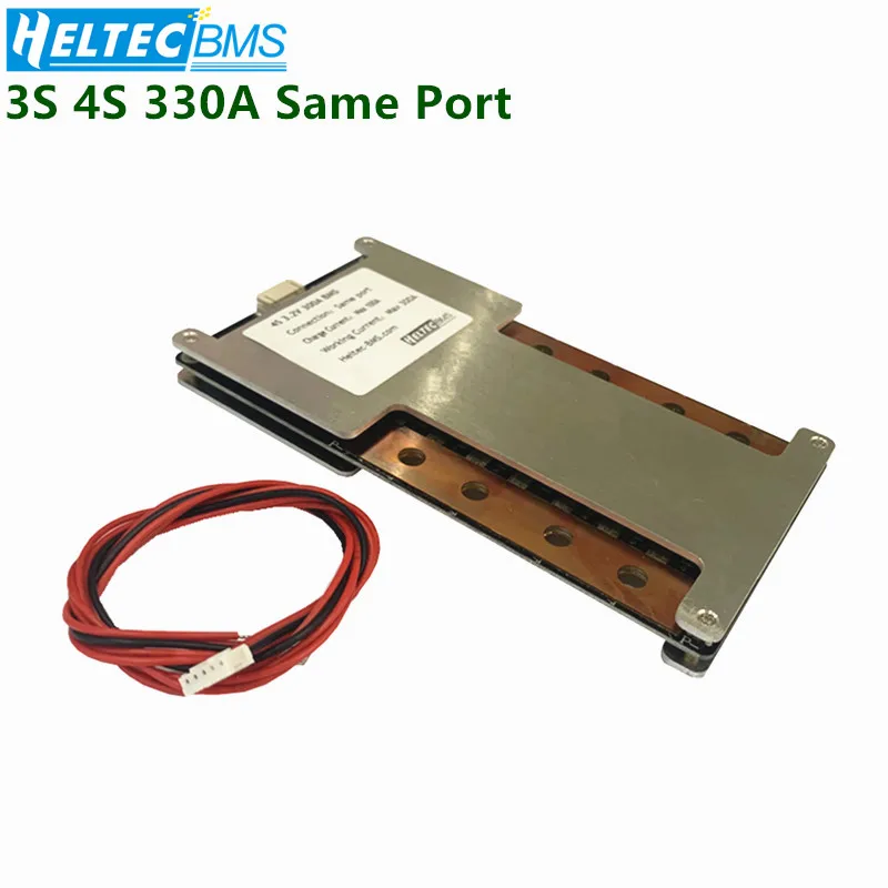
I like this split port 330A load and 100A charge
 www.aliexpress.com
7.59US $ |Bms 3s 4s Balance 100a 120a 160a 200a 300a 380 12.6v/16.8v 18650 Battery Protection Board Li-ion/lifepo4 Ups Inverter/motorcycle - Battery Accessories & Charger Accessories - AliExpress
Smarter Shopping, Better Living! Aliexpress.com
I like this split port 330A load and 100A charge
7.56US $ |12v Bms 300a 3s 4s 300a 330a Continuous Current Lifepo4 Li-ion Battery Protection For Car Start/high-power Energy Storage/rv - Battery Accessories & Charger Accessories - AliExpress
Smarter Shopping, Better Living! Aliexpress.com
")