diy solar

diy solar

How does this BMS cut off charging when a too high level is reached?

Aussiecroc

New Member
Joined
Oct 28, 2019
Messages
109
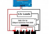
no high inverter.JPG
Can somebody please explain how this BMS can cut off the charging from the solar controller to the battery when the red and the black railroad tracks on the outer sides of the diagram completely bypass the BMS in the middle. Nothing can stop current over filling those batteries unless the outer wires are cut in some way? Am I wrong in my assumption that batteries can overfill and cause runaway etc with voltages as low 13.8 etc What am I missing here? I can see how it can cut off the load in a low voltage situation but what about the high (HVC)?
 
View attachment 2865
Can somebody please explain how this BMS can cut off the charging from the solar controller to the battery when the red and the black railroad tracks on the outer sides of the diagram completely bypass the BMS in the middle. Nothing can stop current over filling those batteries unless the outer wires are cut in some way? Am I wrong in my assumption that batteries can overfill and cause runaway etc with voltages as low 13.8 etc What am I missing here? I can see how it can cut off the load in a low voltage situation but what about the high (HVC)?
I have a similar problem how to stop charging when individual cell is too high.
 
Use a negative bus from the P- on the BMS and wire all your load and charge negatives to the bus instead of to the battery. Think of the BMS as a fancy circuit breaker that cuts off when a cell-level threshold is exceeded.
 
Use a negative bus from the P- on the BMS and wire all your load and charge negatives to the bus instead of to the battery. Think of the BMS as a fancy circuit breaker that cuts off when a cell-level threshold is exceeded.
But if I cut off the battery from charger charger will be shut down
 
I have been wondering about having the BMS control a switch between the solar panels and the controller in order to "stop charging" when conditions (like a cell overcharged or temp near freezing) warrant stopping the "charging"?

I have a Morningstar Tristar MPPT 45 and it warns against disconnecting battery from charger while panels connected: <excerpt from Morningstar Best Practices By Battery Chemistry>


If the battery is disconnected before the solar PV array is disconnected with the TriStar MPPT controller it can sometimes cause irreversible damage to the controller. Therefore most faults and over-voltage protection should be designed to disconnect the PV array first or at the same time as the battery if necessary. A relay driven switch at the PV activated by a battery disconnect is not going to protect the loads or the TriStar MPPT


https://www.morningstarcorp.com/morningstar-best-practices-battery-chemistry/ Page 12 of 20


Morningstar Best Practices By Battery Chemistry - Morningstar Corporation 11/30/19, 5:01 PM


from damage since there is a delay from the battery switch and the PV array switch in which time damage can occur.


There's debate whether or not it is safe to disconnect the battery when PV is hot. In the circuit represented by the OP's schematic, one way to terminate charging and avoid a hot drop would be to have an energized NO relay on the PV positive that is tied to the P- on the BMS. With this setup though, you won't be able to charge during a LVC. These Daly BMS are only practical as a last line of defense.
 
Can somebody please explain how this BMS can cut off the charging from the solar controller to the battery when the red and the black railroad tracks on the outer sides of the diagram completely bypass the BMS in the middle. Nothing can stop current over filling those batteries unless the outer wires are cut in some way? Am I wrong in my assumption that batteries can overfill and cause runaway etc with voltages as low 13.8 etc What am I missing here? I can see how it can cut off the load in a low voltage situation but what about the high (HVC)?
If you get into that situation is it not the case that the BMS is not working correctly? After all it is supposed to balance the cells so that they all have the same voltage. Or are you talking about the overall Battery state? If the latter, it is the responsibility of the MPPT to manage this. You set the various voltages for cutoff, etc.
If you follow Will Prowse's recommendations to operate between 10% and 80/90% SOC, the chance of a battery or cell being over-charged is reduced.
 
>energized NO relay on the PV positive that is tied to the P- on the BMS. With this setup >though, you won't be able to charge during a LVC.

Ah, thats the rub. Thanks.

But as a last line of defense, saving the charge controller is pretty important for a $500 SCC.

So if the BMS cuts an "NO relay on the PV positive", is there a mechanism (likely manual?) to start charging again?
- bypass the NO relay, operator managed?

2 BMS solution possible?
- separate BMS's, one to cut panels (overcharge, freeze*), one to cut load (under current**)?

* BMS has LVC disabled (possible w/o smart BMS?)
** BMS has overcharge, freeze disabled (possible w/o smart BMS?)

Thoughts? Improvements? Shoot down?
 
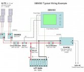
Saw this today - With good modern solid state relays you can turn the solar panel power on and off many times a second like PWM. A controller cut off solar.JPG

that controls the relays and how that presents the power to the batteries. There are people here that use a small 20 amp plasmatronics controller to turn of and on the panels directly to the battery. They have another couple of sets of panels turned off and on with relays that mimic the first set. Dont forget the controller is reading the voltage etc for ALL of them at the battery even though its activating two other sets of panels through relays. Many good SSR can turn off and on fast enough to do a mild PWM.
 
Last edited:
I have a Midnite Classic 200 Solar Controller and they say the same thing about having no battery on the end if there is solar juice going out of the controller. It's a matter of the Charge Profiles... I'm setting both my Controller & Inverter/Charger to these params (24V system, /2 for 12V). Biggest problem is my primary power will be from the LFP pack, while my existing expensive FLA bank becomes the backup but will still need "love".

IN my case Low Volt cutoff is the tricky part because if the LFP cuts off, how to automatically switch to the FLA Bank ?
Then how to recharge the LFP which solar / inverter/charger if cutoff ?
Then to switch back to LFP once charged ?
BUT, then if LFP is charged, then transfer charging to FLA Bank to charge it? (which needs a different profile.... ugh)
The things to sort out, a potential Frankenstein of electrical spaghetti... enough to cause Brain Pain !

Parameters I am setting
Bulk Voltage : 28V - 29.2V
- Absorption Voltage *: 28V - 29.2V Absorption Time 0-15 min
- Float Voltage *: 26.6V - 27.6V
- Equalize *: OFF or as short time possible @ float voltage
VOLTAGE CUTOFFS: Low Voltage: 22V-24V. High Voltage: 29.2V
* not necessary
 
Saw this today - With good modern solid state relays you can turn the solar panel power on and off many times a second like PWM. A controller View attachment 2882

that controls the relays and how that presents the power to the batteries. There are people here that use a small 20 amp plasmatronics controller to turn of and on the panels directly to the battery. They have another couple of sets of panels turned off and on with relays that mimic the first set. Dont forget the controller is reading the voltage etc for ALL of them at the battery even though its activating two other sets of panels through relays. Many good SSR can turn off and on fast enough to do a mild PWM.
Do you have recommendation for good SSR. Those I find on Amazon have poor reviews.
 
Im thinking there is going to be a lot of discarded dead lithium cells at the tip in the near future
 
Back
Top