diy solar

diy solar

How to AC couple Enphase IQ8 w/Battery Storage to Schneider XW Pro 6848 w/rack batteries, off-grid?

I'm curious about the grid profile and other experiment setup as well. A couple of the numbers and setup don't make sense.

How were the battery charge settings chosen? Can you tell the XW to have maximum shift of 63 and use relay disconnect above that?

Why did FW start at 98%? Is it because of the low battery charge current? Did you try with 90% which is the recommended setting for XW? Does XW use the grid code F-W settings to determine the shift range? (I'm going off this document https://www.solar-electric.com/lib/wind-sun/Conext-XW-Pro-SW-AC-Coupling-Guide.pdf)

View attachment 178072
View attachment 178073
I have limited time and a main job to earn money, so testing will be in small incremental steps as I have spare time.

Grid Profile: IEEE 1547 2018 for both IQ8's and XW-Pro

The XW-Pro AC coupling guide you've cited is out-of-date and the p(f) configurability is no longer available in the XW-Pro latest firmware I have.
There are no properties or config parameters to tie p(f) to SOC or battery voltage over time and set an upper limit for f.

There were 2 key issues I wanted to test:

- are there micro-inverters that can be AC-coupled with XW-Pro?
- why are AC-coupled IQ8 inverters shutting down without restarting?
 
From the EG4 doc/video, it's unclear if they have iQ8 AC coupling working off grid. Most grid-interactive hybrid inverters have no issue AC coupling with iQ8's when on grid.
Would like to know how Lux Power or EG4-18kvp can be AC coupled with IQ8's and handle on-grid to off-grid transition.

- FW enabled or disabled ?
- connected to generator input or load side ?
- wait for full PV production, switch all loads off and see how fast the IQ8's can be shut down without tripping the inverter?
 
I have limited time and a main job to earn money, so testing will be in small incremental steps as I have spare time.

Grid Profile: IEEE 1547 2018 for both IQ8's and XW-Pro

The XW-Pro AC coupling guide you've cited is out-of-date and the p(f) configurability is no longer available in the XW-Pro latest firmware I have.
There are no properties or config parameters to tie p(f) to SOC or battery voltage over time and set an upper limit for f.

There were 2 key issues I wanted to test:

- are there micro-inverters that can be AC-coupled with XW-Pro?
- why are AC-coupled IQ8 inverters shutting down without restarting?
Hmm so if they removed the configuration does that mean there is no control at all on the XW side, and any tuning has to be done on the inverter side? Does it perhaps use the grid profile set on the XW as the frequency shift limits? As a zero export battery inverter not participating in assisting grid I don’t think XW needs to comply with any F-W function.

Potentially you could add a frequency -based relay that disconnects Enphase on extreme frequency shift to prevent locking them down, if the XW cannot be forced to stay within a frequency range.

I posted a similar test plan to what you seem to be interested in.

Post in thread 'Disadvantages of AC coupling - poor battery charging?'
https://diysolarforum.com/threads/d...pling-poor-battery-charging.72294/post-918150
 
Hmm so if they removed the configuration does that mean there is no control at all on the XW side, and any tuning has to be done on the inverter side? Does it perhaps use the grid profile set on the XW as the frequency shift limits? As a zero export battery inverter not participating in assisting grid I don’t think XW needs to comply with any F-W function.
Correct, there are no rules and regulations how the off-grid inverter has to perform in an off-grid micro-grid config.
I do not know any ESS inverter that has a configurable off-grid AC coupling profile, separate from the grid-tied profile.

Potentially you could add a frequency -based relay that disconnects Enphase on extreme frequency shift to prevent locking them down, if the XW cannot be forced to stay within a frequency range.
Too complicated, why detect the change in frequency if the XW-Pro has a trigger capability on battery high voltage, including hysteresis. What it does not support is something similar for closed loop SOC. There is no hysteresis on SOC anywhere. Disable FW and keep f = 60 Hz constant.

I posted a similar test plan to what you seem to be interested in.

Post in thread 'Disadvantages of AC coupling - poor battery charging?'
https://diysolarforum.com/threads/d...pling-poor-battery-charging.72294/post-918150
Was my goal from the beginning to test the IQ8 problems by starting small.
IQ8 AC coupling
 
I thought people had trouble just getting IQ8 to connect and remain connected at 60 Hz. I thought it was the anti-islanding.
If they do connect reliably and only disconnect with frequency shift, that is at least usable.
I thought so too. But when the grid-tied ESS inverter with full PV production and no load other than backfeed into the grid suddenly gets disconnected from the grid, the PV current needs a place to go. Inverter raises the frequency, beyond 62.5 Hz and the IQ8's shut down for the rest of the day, never connecting to the micro-grid after 5 minutes. We may have misinterpreted this IQ8 behavior as anti-islanding protection.

Will try to setup a test next week with IQ8's just for this case.

Here is what's so bad: the IQ8's disconnect for the rest of the day and I want to understand why.

Enphase could easily fix this: provide an AC-coupling profile that does not disable the IQ8 inverter on f > 63.5 Hz.
Hoymiles can obviously tolerate a raise in f(p) to 66 Hz or more.

Here is a test worth doing: connect an IQ8 to a VFD (variable frequency drive) with an additional load such that no power is backfed into the VFD.
Then gradually raise the frequency and observe IQ8 output current/power to react to the frequency shift. If I find time next week I might try this to really understand how IQ8's react to a frequency shift.
 
I've played with VFD (feeding a HyPot), wasn't using a scope, but I doubt waveform looks good to a GT PV inverter.

Not sure if Sunny Island can be commanded to new frequency on the fly. Could configure a Sunny Boy to do frequency-watts ramp from 60 Hz to 64 Hz, then vary load to make frequency shift occur for IQ8 to see.
 
Too complicated, why detect the change in frequency if the XW-Pro has a trigger capability on battery high voltage, including hysteresis. What it does not support is something similar for closed loop SOC. There is no hysteresis on SOC anywhere. Disable FW and keep f = 60 Hz constant.
Not sure what you're proposing. Trigger a relay that disconnects when the voltage or SoC is at a level where XW can't absorb the excess power from microinverters? Does that approach work? If so, what is the advantage of FW vs this approach?

The idea with the frequency-triggered relay is to attempt to still use FW most of the time (and maybe get intermediate control), and then disconnect the microinverter if the grid forming microinverter misbehaves.

What is raising the frequency, the IQ8 or the XW? IQ8 use Group 1 anti-islanding:
1700191734106.png

Does the XW know that it is the boss quickly enough after grid disconnect and shouldn't participate in Group 1 (if that is the method it uses).

Finally figured out what Droop Slope means (from a NREL paper). If possible to customize the XW grid profile maybe set a sharper than usual droop slope. Something like 5% is the default in 1547 2018 if I google. That gets up to 63Hz which is dangerously close to pissing off the Enphase.

1700191183201.png
 
Sunny Island: That would be a great test, having an inverter where the FW shift up ramp can be specified, especially the end point and a ramp slope or gradient over time.
 
Not sure what you're proposing. Trigger a relay that disconnects when the voltage or SoC is at a level where XW can't absorb the excess power from microinverters? Does that approach work? If so, what is the advantage of FW vs this approach?

The idea with the frequency-triggered relay is to attempt to still use FW most of the time (and maybe get intermediate control), and then disconnect the microinverter if the grid forming microinverter misbehaves.
Exactly! The XW-Pro has a built-in auxiliary output port that can be triggered by a battery voltage at a defined level. This is exactly the approach that works in Franklin WH, EP Cube and other inverters. When Sol-Ark AC generator is tied to SOC, the relay will open and disconnect the PV array.

The idea of FW is a graduated approach to power curtailment. PoCo's can raise the grid frequency to 60.2 Hz and see if they get a reduction in PV power generation, then they raise it a little bit more. But this is not the way most ESS inverters work. The ones I know do not have a FW function over SOC and over time.

As my IQ8 test has shown, all it takes is a 300W imbalance between production and consumption to disable an IQ8. Real PV production and real loads have much higher imbalances.
 
The idea of FW is a graduated approach to power curtailment. PoCo's can raise the grid frequency to 60.2 Hz and see if they get a reduction in PV power generation, then they raise it a little bit more. But this is not the way most ESS inverters work. The ones I know do not have a FW function over SOC and over time.

I'm not sure the FW intermediate power states are all that useful for rapid response when the mandatory response speed is something like 5s (saw it yesterday when reading the documentation).

However it is likely very useful as a graceful way to go to 0W, without having to risk forcing the microinverter off through a path that it might not come back from, or has a tiny chance of damage.

It could also be very useful for slower responding goals. For instance, if you have too much AC size for the charger/inverter/battery rating and want to cut it down to 50% to stay within design rules. And in the morning, it could be set to 100% b/c there isn't that much sun, going down to say 50% by mid day when there's too much. Sure, you could also use for example the proprietary inverter interface to do this (Hoymiles can do this pretty granularly, down to microinverter if not port level), but FW seems OK too.
 
Try configuring XW to stop frequency shift at 61.25 Hz, regardless of whether it was successful in curtailing AC coupled PV.
That should force it to stop before IQ8 goes down for the count. Maybe IQ8 is just too slow to ramp down.

Try configuring XW to much slower frequency ramp. Gives IQ8 more time.
Would like to do this, but there are no controls in InsightLocal and XW-Pro firmware to do this, or I don't know where to find them.
IQ7's are much faster than IQ8's responding with a ramp down to a raise in frequency.
 
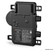
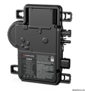
What does it take to get an IQ8 working?
If somebody sent me one and all I have to do is connect PV and AC, I could try exercising it on Sunny Island, document its behavior.
 
No need for combiner AFAIK.

Did not know about the MC4 adapter. Dunno if a special disconnect tool is needed for it.

The trunk cable, you can probably find extras on Craigslist. I think there are some special widgets like end of branch terminators… or you could electrical tape/wirenut it up.

 
Something like this?


Then apparently I cut and splice that in a junction box.

No combiner need? If I'm not accessing data?


Plus this for MC4

Older versions of the IQ needed that converter pigtail to MC4, modern versions now have MC4 standard as DC input.
Screenshot from 2023-11-17 08-49-57.png
vs
Screenshot from 2023-11-17 08-50-54.png

Just give it 240 & PV panel and "it will work" [famous last words]
At startup there will a RED led for 5 minutes and then it will turn orange, meaning it found the grid but no communication with an envoy/communication gateway.
With communication it will turn green.
If you want to set grid profiles etc you will need an envoy to do so.
 
What was the point of the DC adapter? To make it slightly easier to work with non MC4 panels while also getting Enphase more revenue from selling yet another custom cable?
 
What was the point of the DC adapter? To make it slightly easier to work with non MC4 panels while also getting Enphase more revenue from selling yet another custom cable?
Since the cable was included with the inverter, I don't think revenue was the reason.
 
Back
Top