diy solar

diy solar

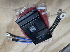
How to connect the "black" style JK-BMS with the short B- and P- leads?

I’m using ones similar to what you linked, with heat shrink. I bought a pack with various sizes, but I think those Wirefy ones should be good.
 
Do not ask me how long I've been "building" my first battery.
Of course, it might make you feel better. And me worse!
I've had my cells for 2 years....

It took me two years to build a shed and move my inverter in it after I decided I wasn't using batteries under my home roof. My cells sat disconnected.
 
Last edited:
It took me two years to build a shed and move my inverter in it after I decided I wasn't using batteries under my home roof. My cells sat disconnected.
I completely understand the concern.
 
Trimming just barely does the trick, thanks for the suggestion!
Those Wirefy are the best connectors for balance leads that I have seen. But I was just looking at what you mean about trimming the insulation. I got it to move some when I heat shrunk them but I still think they might need some trimming.
 
Those Wirefy are the best connectors for balance leads that I have seen. But I was just looking at what you mean about trimming the insulation. I got it to move some when I heat shrunk them but I still think they might need some trimming.
Didn't even occur to me to try heat shrinking them. I'll give that a shot too.
Edit: Didn't make a difference, still had to trim them with a razor.
 
Last edited:
I cannot believe how long this process is taking me.
It’s a learning experience, nobody here picked it up in the first hour. Do it yourself also means do it your own way, there’s no right or wrong way to attach two wires together, as long as the result can carry the required current.

Have a little patience, take each challenge as a learning experience, and don’t stress about it.
 
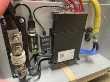
Since the cables are 7AWG I used 6AWG luges but used a 6AWG and a 8AWG die on the opposite side in the hydraulic crimper. These are some of the items in the picture:

SELTERM 10pcs 6 AWG-3/8" Stud... https://www.amazon.com/dp/B09CGW75VZ?ref=ppx_pop_mob_ap_share

SELTERM 10pcs 6 AWG-3/8" Stud... https://www.amazon.com/dp/B09CGW75VZ?ref=ppx_pop_mob_ap_share

Fastronix 5/16" Stainless Steel...

IMG_0956.jpegIMG_0954.jpeg
 
IIRC the BMS wires are 7 AWG and when I was crimping them, they fit snugly into the 4 gauge lug. The single wires I used 6 AWG lugs.
Wires are 7 AWG. The terminal I tried is slipping on is rated for 4 to 6 AWG so slightly smaller than a regular 4 AWG however 7 AWG is 3.665 mm diameter (10.6588 mm²) and 4 AWG is 5.189 mm (21.15 mm²). 2 AWG is 6.543 mm (33.63 mm²). Biggest problem I saw was getting all those tiny wires into the 4 AWG terminal. Very tight and my biggest concern would be over crimping the connection leading to shear of strands leading to reduced connection strength (possible pull test failure) and reduced conductivity.

A good hydraulic crimper like the Temco I use that has plus and minus dies would make the 2 AWG my choice.
 
Tiny zip tie around the wires, slide terminal on then snip the zip tie.
Video (with obnoxious music)
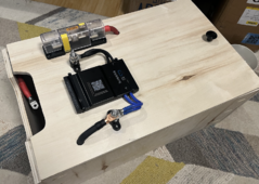
I dug thru my terminals and found some 6 AWG and 4 AWG. I still think with both wires into a 4 AWG it will be overcrimped.

Using the 6 AWG with a minus size die first on a single cable would work out nicely. Then possibly use the standard size die. I might find out soon, I'm putting together a box with this style BMS.
 
@Skypower
That's beautiful work. If you don't mind me asking:
Those RS485 / USB pieces, Is that a CANbus to inverter connection?
How did you attach those smaller pieces to the board? They look nice all aligned like that. Just glue?
 
@Skypower @offgrid-curious

(offgrid-curious not sure you did the same placement of the T-class fuse but adding you just in case)

Regarding your T-class fuse placement, quite a few people on this forum say the T-class fuse needs to be mounted as close to the main battery positive terminal as possible. Some say within 5-7 inches, but basically the closer the better. Here are examples of 3 posters discussing this:

"you want the fuse as close to the power source as possible. If the fuse is at the inverter, it will not prevent a fire if there is a short between the fuse and the battery."

"All battery banks should have A T-class or similar placed as close to wherever positive is connected. Having an unfused positive wire going from a battery bank is risking a short due to a damaged cable and is a bit like putting a AC breaker by the outlet and not in the breaker box."

"Fusing the wire as close to the battery as possible. Remember fusing is for protecting what comes after it. Which would be your inverter."

Anyway, just thought I'd mention that. Your layout looks beautiful tho!

I should add, I'm just repeating what I've heard others say, including the guy who designed my system @ncsolarelectric. Personally I'm not an expert so don't take this as me suggesting one way or the other. (y)
 
Last edited:
I had cropped the class T fuse out of my original picture. Here's a larger view of my inner battery box that includes it:

20240428-18-31.52.png

My fuse is connected directly to the positive cell terminal. This inner wooden box is going inside of an insulated custom fabricated metal enclosure (which is shipping out this week!).

My battery build is heavily inspired by what @Horsefly did in his insulated battery build: https://diysolarforum.com/threads/horseflys-2nd-cabin-battery-build.68711/.
 
He's got the T-Class fuse as close as possible to the negative terminal, what's the difference?
A fuse for overcurrent protection can be mounted anywhere in the circuit, the current is the same throughout the circuit.

For short circuit protection, the fuse needs to be mounted as close to the battery as possible. As long as the chassis is not connected to negative side of the circuit, the fuse can be on the negative terminal. For example a metal battery box that is connected to battery negative can not have the fuse located on the negative part of the circuit. It would need to be on the positive side in case there was a short to the battery box.

If the box is not connected to battery negative or a vehicle chassis is not to negative is another example, then the fuse is perfectly fine mounted on the negative terminal.
 
If you do a search on the terms "positive" and "t-class" on the forum, you'll find a bunch of people suggesting the t-class fuse should be as close to the positive terminal of the battery as possible. Also that's how my system was designed by Todd the CEO at @ncsolarelectric. Could be they are all wrong. I just threw a couple quotes from others on the forum up for @Skypower in case they were helpful for him, he's free to disregard them if he feels they are incorrect. I'm not here claiming I am any authority, just trying to help and be helped by others who know more than I do.
 
Last edited:
Back
Top