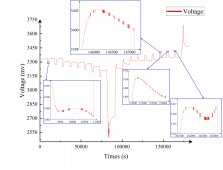
A strange situation occurred when I performed SOC-OCV testing on a LiFePO4 cell with a capacity of 105Ah using the incremental OCV method.
The test uses a current multiplier of 0.2C, a resting time of 2h, an ambient temperature of 25°C, a charge cutoff voltage of 3.7V, a cutoff current of 0.02C, and a discharge cutoff voltage of 2.5V. To ensure complete discharge, it is set to rest for 5min after discharge to 2.5V, and then discharge again to 2.5V using a current of 5A. This last process of low current discharge will Repeat three times.
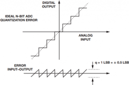
In some discharging or charging sections, a non-monotonic variation of the voltage curve was observed. As shown in the attached figure, during discharge, the voltage appears to increase and then decrease. While in charging, the voltage decreases and then increases. The voltage even appears to be monotonically decreasing when the eighth charge is performed (the polarization establishment phase is excluded). According to normal perception, this should not happen. The battery was almost new and the charging and discharging equipment had not failed during operation, everything was well connected, but there was an average error of about 6mV in the measurement accuracy. However, through testing, this measurement error is not accidental, but is steadily present. Therefore, I think that the sensor error is not the cause of the error in the measurement results.
I have reviewed many literature sources and have not been able to find any relevant cases or explanations. I would like to ask for help if anyone has also encountered this situation or can give an explanation?


