diy solar

diy solar

JA Solar Panel Module Grounding Restriction with MPP Solar Non-Isolated Inverters

ChrisG-UK

New Member
Joined
Dec 20, 2023
Messages
8
Location
UK
This is my first post to a forum so please excuse any errors.

I have just ordered two MPP Solar PIP Max 11kw Inverters and was planning to use these with 24 x JA Solar JAM54D41-435/LB Mono N-Type bi-facial panels. However, upon reading the installation manual for JA panels they say that their modules must have the DC Cathode (-ve) connection of the array grounded vis:

"JA Solar Modules should only be used in configurations where the DC cathode of the Modules array is connected to ground. Failure to comply with this requirement will reduce the performance of the system and invalidate JA Solar’s Limited Power Warranty for Modules.”

The MPP Solar PIP Max AIO inverter manual states:

“WARNING Because this inverter is non isolated, only three types of PV modules are acceptable: single crystalline, poly crystalline with class A rated and CIGS modules. To avoid any malfunction, do not connect any PV modules with possible current leakage to the inverter. For example, grounded PV modules will cause current leakage to the inverter. When using CIGS modules, please be sure NO grounding.”

I queried this with both MPP Solar and JA Solar. MPP responded quickly and after a couple of brief email exchanges they confirmed that the JA Solar panels should not be used with their PIP Max AIO inverter. Unfortunately JA Solar have not responded at all despite reminder emails.

Grounding the JA panels does appear to be a total No-No to the MPP Inverter. It also sounds like not grounding the DC connection of the array doesn't seem to be a safety or damage issue to the JA array but is one of an impact on the performance of the panels. JA only don't guarantee the performance warranty, it doesn't affect the normal hardware product warranty. I don't understand, the JA panels are mono crystalline and seem to otherwise comply with the MPP inverter requirements if not grounded. So, why would not grounding them affect performance?

Looking at other manufacturers they don't seem to have the same restriction? The JA Solar panels are on offer here in the UK at a very good price which is why I favour using them together with the fact that they are bi-facial and would probably aid power power production in the winter periods here. If I just connect these panels without the grounding will I see a degradation in performance of the panels? Or, am I best to just steer clear of JA Solar panels?

I'd be interested if anyone can offer some advice? Especially if there are users out there that have MPP or similar AIO HF Non-Isolated inverters in use with JA Solar panels with and without the required grounding connection.

Many thanks in anticipation of your responses.

Chris
 
This is my first post to a forum so please excuse any errors.

I have just ordered two MPP Solar PIP Max 11kw Inverters and was planning to use these with 24 x JA Solar JAM54D41-435/LB Mono N-Type bi-facial panels. However, upon reading the installation manual for JA panels they say that their modules must have the DC Cathode (-ve) connection of the array grounded vis:

"JA Solar Modules should only be used in configurations where the DC cathode of the Modules array is connected to ground. Failure to comply with this requirement will reduce the performance of the system and invalidate JA Solar’s Limited Power Warranty for Modules.”

Older installation manuals have this, I did not see it in current manuals. https://www.jasolar.com/index.php?m=content&c=index&a=lists&catid=70

I run JA Solar, the frames are grounded to grounding system, that is all there is for grounding. I commonly pull over STC in cooler temps with very good sun.

The MPP Solar PIP Max AIO inverter manual states:

“WARNING Because this inverter is non isolated, only three types of PV modules are acceptable: single crystalline, poly crystalline with class A rated and CIGS modules. To avoid any malfunction, do not connect any PV modules with possible current leakage to the inverter. For example, grounded PV modules will cause current leakage to the inverter. When using CIGS modules, please be sure NO grounding.”

I queried this with both MPP Solar and JA Solar. MPP responded quickly and after a couple of brief email exchanges they confirmed that the JA Solar panels should not be used with their PIP Max AIO inverter. Unfortunately JA Solar have not responded at all despite reminder emails.

Grounding the JA panels does appear to be a total No-No to the MPP Inverter. It also sounds like not grounding the DC connection of the array doesn't seem to be a safety or damage issue to the JA array but is one of an impact on the performance of the panels. JA only don't guarantee the performance warranty, it doesn't affect the normal hardware product warranty. I don't understand, the JA panels are mono crystalline and seem to otherwise comply with the MPP inverter requirements if not grounded. So, why would not grounding them affect performance?

Looking at other manufacturers they don't seem to have the same restriction? The JA Solar panels are on offer here in the UK at a very good price which is why I favour using them together with the fact that they are bi-facial and would probably aid power power production in the winter periods here. If I just connect these panels without the grounding will I see a degradation in performance of the panels? Or, am I best to just steer clear of JA Solar panels?

I'd be interested if anyone can offer some advice? Especially if there are users out there that have MPP or similar AIO HF Non-Isolated inverters in use with JA Solar panels with and without the required grounding connection.

Many thanks in anticipation of your responses.

Chris
Run positive and negative, plus an EGC back to system grounding electrode or busbar. It will work just fine. My system is JA Solar with non isolated MPP Solar LV6548's.
 
Some PV panels are more subject to PID than others.
DC coupled systems usually have PV- grounded. Older transformer-type grid-tie inverters did too.
Some PV panels (notably early ones from SunPower) had PV cells with different type of doping, and suffered PID with negative grounding. Positive grounding with transformer type inverter allowing that solved the problem.

Most panels these days are resistant to PID. If a panel says only negative ground is allowed, I wouldn't want to use it with transformerless inverter/SCC.

PID is partly reversible, partly irreversible. There were gizmos created to bias the PV array negative (or positive) at night, to drive ions back out of the PV junction.

If you've already got those panels, consider connecting them to a stand-alone SCC that does provide negative ground.
Using them with the MPP PIP may cause them to rapidly degrade, in which case better to not do that and ruin them.
 
Older installation manuals have this, I did not see it in current manuals. https://www.jasolar.com/index.php?m=content&c=index&a=lists&catid=70

I run JA Solar, the frames are grounded to grounding system, that is all there is for grounding. I commonly pull over STC in cooler temps with very good sun.


Run positive and negative, plus an EGC back to system grounding electrode or busbar. It will work just fine. My system is JA Solar with non isolated MPP Solar LV6548's.
Hi Zwy,

Thanks for that. The manual I have is Version 1.3 Oct 18th, 2019 so, five years on now and a lot has definitely changed. I should have checked that! As Hedges says, most panels these days are resistant to PID so I guess the current panels I'm looking at have greatly improved in this area. As you say, there is no mention of grounding either of the DC connections in the latest installation manual. All good therefore I reckon. I really do want to use these panels.

Regarding running an EGC back to ground the array frames. I have just the one main ground/earthing point BusBar where the grid connection is and I believe this is where you recommend I should connect the array EGC to. The inverters will be grounded here. I was thinking of grounding the array frames and steel ground mounts etc. to a completely separate, new ground electrode installed by the panels. I think this might be better than to risk feeding the energy from a lightening strike back to all my inverters etc.? I shall be installing lightening /surge protection on the DC legs from the panel strings. Or, should I also add an EGC from the new array ground electrode back to the system ground? As well as the lightening risk, could this potentially introduce ground loops for any induced AC? I have to admit that the grounding aspect confuses me somewhat. My thought to ground the array frames separately is because there is no connection whatsoever to DC or AC? Sorry if I'm rambling, Does this make sense?

Thanks for your help. :)
 
Hi Zwy,

Thanks for that. The manual I have is Version 1.3 Oct 18th, 2019 so, five years on now and a lot has definitely changed. I should have checked that! As Hedges says, most panels these days are resistant to PID so I guess the current panels I'm looking at have greatly improved in this area. As you say, there is no mention of grounding either of the DC connections in the latest installation manual. All good therefore I reckon. I really do want to use these panels.

For what panels cost, I would not be concerned with PID degradation anyway. I find it amusing some will buy used panels that are older, might be subject to high PID degradation and had been used on SCC's that were not anti PID and never give it a second thought because the panels were "cheap".


Regarding running an EGC back to ground the array frames. I have just the one main ground/earthing point BusBar where the grid connection is and I believe this is where you recommend I should connect the array EGC to. The inverters will be grounded here. I was thinking of grounding the array frames and steel ground mounts etc. to a completely separate, new ground electrode installed by the panels.

No, only an EGC back to system grounding.

I think this might be better than to risk feeding the energy from a lightening strike back to all my inverters etc.?

Auxiliary ground electrode can make it much worse due to gradient pulse.

I shall be installing lightening /surge protection on the DC legs from the panel strings. Or, should I also add an EGC from the new array ground electrode back to the system ground? As well as the lightening risk, could this potentially introduce ground loops for any induced AC? I have to admit that the grounding aspect confuses me somewhat. My thought to ground the array frames separately is because there is no connection whatsoever to DC or AC? Sorry if I'm rambling, Does this make sense?

Non isolated inverter can put AC on the PV frames. Anything in the system that can conduct electricity such as breaker panels, junction boxes and panel frames that are metal are required by NEC to be bonded to system grounding.


Thanks for your help. :)
The topic of extra ground rods, no EGC back to system grounding and other topics related to grounding come up quite often here.

Watch the video in this post, Mike Holt is one of the best and the reasons for only a single grounding point is explained when it comes to PV arrays.
 
The inverters will be grounded here. I was thinking of grounding the array frames and steel ground mounts etc.
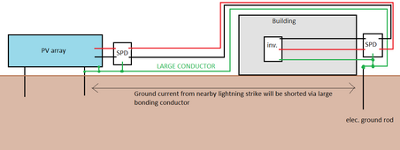
If ground mount structure sits on metal beams driven or concreted into earth then your array is already effectively grounded (from lightning point of view) and extra ground rod will not change things by much. You need to install surge protectors at both the array side and inverter side and bond the array ground point to your electrical entrance ground rod/point with a large (#4 - 4/0) conductor to conduct the bulk of lightning induced ground potential rise and put inverter side surge protector close to electrical ground rod and elec. service entrance (single point ground).

pv-ground-bond.png
 
Are you sure SPD at array is beneficial in any way? Isn't it harmful?

If PV+/- are thought of as a whip (voltage) antenna, induced current causes large voltage swing relative to earth at PV array end, but probably not much current flows.

With SPD at array, it fires an clamps PV+/- to about 1000V relative to ground, forming a loop antenna, and current is forced through PV+/- to building. I think that is more current that SPD at building has to deal with.

Maybe best protection would be a "fence" of ground rods around array, another around building. Conductor between them. Puts them both inside an equipotential area. (could have been fence all around both, but for large distance, I'm thinking conductor bonding them together.)
 
Are you sure SPD at array is beneficial in any way? Isn't it harmful?
No its more harmful to leave PV+/- floating because induced voltage spike (from ground bonding conductor current flow) will blow frame to solar cell insulation barrier. SPD clamps that.
With SPD at array, it fires an clamps PV+/- to about 1000V relative to ground, forming a loop antenna, and current is forced through PV+/- to building.
Majority of current is forced via large bonding conductor. Some current will flow via PV+/- and that's why it has to be clamped by at least 10kA capable SPD but more is better.
Maybe best protection would be a "fence" of ground rods around array, another around building. Conductor between them. Puts them both inside an equipotential area.
This is best but expensive. Usually done at broadcast transmitter sites.
 
For what panels cost, I would not be concerned with PID degradation anyway. I find it amusing some will buy used panels that are older, might be subject to high PID degradation and had been used on SCC's that were not anti PID and never give it a second thought because the panels were "cheap".
Totally agree. These JA panels new are just £82.00 GBP each for 435w, bifacial, all black panels. High PID degradation seems to be much lower on recently manufactured PV panels. The cost to replace all the panels in say, five years wouldn't be a lot and probably would be a benefit as much higher outputs would be available then.
 
  • Like
Reactions: Zwy
No, only an EGC back to system grounding.
This is easy for me to do as the main support posts for the unistrut frames are to be timber (not installed yet). Also, it provides adherence to NEC rules to ground back to a single point. However, what AntronX is interesting as what is the case if the supports were steel? The whole PV panel support system would be grounded by the nature of the construction.
 
Non isolated inverter can put AC on the PV frames. Anything in the system that can conduct electricity such as breaker panels, junction boxes and panel frames that are metal are required by NEC to be bonded to system grounding.
Understood.
 
The topic of extra ground rods, no EGC back to system grounding and other topics related to grounding come up quite often here.

Watch the video in this post, Mike Holt is one of the best and the reasons for only a single grounding point is explained when it comes to PV arrays.
Yes, this topic does seem prolific. That's what I found confusing.

Now! the question of neutral earth bonding and the TNS system used by the grid in the U.K. That also causes much confusion. Maybe another day when my system is installed. :)
 
bond the array ground point to your electrical entrance ground rod/point with a large (#4 - 4/0) conductor
Hi AntronX, #4 - 4/0 - this is AWG yes? and equates to 21.1506 sq mm. csa.? Sorry, I'm not that familiar with AWG. In the U.K. it's all sq.mm. The main earth connection (Ground) at the grid entrance point is 16.0mm squared at my property. Live and Neutral conductors are 25.00mm squared - 240v 100A TNS system - Earth and Neutral bonded externally in the feed to the property. As such I would propose to maintain 16.00mm2 for the EGC cable. Am I correct?
 
As such I would propose to maintain 16.00mm2 for the EGC cable. Am I correct?
That's between 5 - 6AWG. Bigger is better but it's a tradeoff on price vs. how much peak current will travel over your PV cable and surge protectors. You can coil some PV cable into a loop to increase resistance and impedance which would force more lightning strike current over your ground conductor.
 
Last edited:
I have used inductors in a filter circuit (for output of a magnetic field sensor having excitation signal), but my concern is the very magnetic fields I'm trying to protect against could couple into it, injecting noise (or in the case of your lightning strike, destructive current.) I used a shielded inductor (ferrites), but for high energy threats I assume that saturates and becomes ineffective.

How about this - use two inductors in series, wound in opposite directions, so somewhat farther field induces cancelling voltages?
For the PV wire, that would be two coils of say 10 turns, then flip one coil over so one is clockwise and the other counter-clockwise.

Maybe take a clue from the "Boxer" engine design: 4 coils inline, flipped so windings are counter-clockwise, clockwise, clockwise, counterclockwise.
 
I thought about counter wound coils but would they mutually couple and cancel out their inductance? I wonder how bad extra inductive surge pickup via loops will be compared to total PV wire length inductive pickup. I think MOVs will catch RF inductive spike and extra loop resistance will help limit low frequency tail current. Or the loop can be oriented horizontally in relation to earth to reduce magnetic coupling.
 
This is easy for me to do as the main support posts for the unistrut frames are to be timber (not installed yet). Also, it provides adherence to NEC rules to ground back to a single point. However, what AntronX is interesting as what is the case if the supports were steel? The whole PV panel support system would be grounded by the nature of the construction.
My array is supported by 6 inch SCH80 steel poles with 36 inch diameter hole filled with concrete. https://diysolarforum.com/threads/mt-solar-mount-review.51255/ I could get some gradient pulse from a nearby lightning strike due to this reason. I wanted seasonal tilting array and specific ground clearance and the MT Solar fit the bill. I'm currently getting ready for 2 more arrays to be installed, both will have MT Solar mounts. I almost went with Sinclair but these mounts were used and cheap. Prior owner had collected on storm damage.
 
I thought about counter wound coils but would they mutually couple and cancel out their inductance? I wonder how bad extra inductive surge pickup via loops will be compared to total PV wire length inductive pickup. I think MOVs will catch RF inductive spike and extra loop resistance will help limit low frequency tail current. Or the loop can be oriented horizontally in relation to earth to reduce magnetic coupling.


With separation, much of the field doesn't pass through each other. (something operated at resonance, like stealing power from overhead lines, could be different.)

We're playing with coils about 1 ~ 2 meters square, each made with the 8 conductors of Ethernet cable. I think but don't have much confirmation yet that coupling between the two coils is much less than coupling among the 8 wires.

One scheme is two such coils. Another has four coils, think it will be 12 turns, 5 turns, 5 turns, 12 turns or close to that all wired in series. Supposed to have larger uniform field area.

Project is driven aggressor coils to measure instrument sensitivity, also test effectiveness of MFC system. So our applied field being fairly uniform should represent distant aggressors, while MFC system is like the one deployed.
 
Back
Top