diy solar

diy solar

LFP cell balancer shunt DIY

AntronX

DC Powered
Joined
Oct 24, 2021
Messages
1,466
Location
South FL
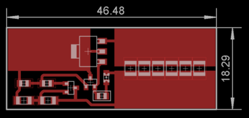
Simple voltage shunt circuit to balance LFP cells. R8 and R9 sets shunting threshold to 3.45V and placed away from heat generating parts to reduce voltage drift. Shunting current should be around 0.38A should be enough to keep 100A cells in balance. Single sided PCB no holes or vias, easy to etch yourself with toner transfer method. I plan to clip these directly onto cell terminals using alligator clips. Edit: Transistor T3 is BSP43 1A NPN.
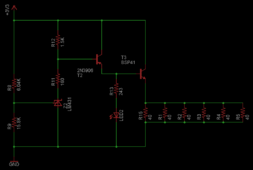
battery shunt schematic.PNG

battery shunt.PNG
 
Last edited:
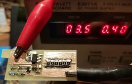
Worked on first try. Helps that this was LTSpice tested design I made 10 years ago. After 10 minutes at 3.6V 0.42A transistor was at 75°C and resistors at 90°C. Now I need to make 15 more of them. Will have to use reflow oven soldering. Idle consumption 0.8mA at 3.3V and 5mA at 3.4V. Shunting current starts ramping up at 3.43V and reaches maximum at 3.45V.

20240424_160937_resized.jpg
 
Last edited:
What’s the possible failure mode if things go wrong?

Short to ground and pop a fuse to be installed later on?
 
Short what to ground? Worst that can happen is transistor getting stuck on and discharging cell to zero unless caught in time.
 
Last edited:
Gotcha, nothing like simulator being proven true.
Yes it's certainly nice when it works just as predicted. I got this circuit idea from the creator of MiniBMS a while back at diyelectriccar forum. I changed component values and simulated it to make it work just how I wanted. For higher amperage and less balanced cells I may have to re-design it with a MOSFET and larger load resistor.
 
Back
Top