diy solar

diy solar

Magnum MS4448PAE charger quit working.

Jack Rabbit Off Grid

Solar Enthusiast
Joined
Sep 6, 2021
Messages
478
So the other day I decided to wire up my Magnum A/C input. Got that all done and set all the charger settings and gave it a try with my generator all seam to work fine.

I’m only running off a 120v generators and wanted to turn off the charger so more power would bypass to the house. so I used the charger on/off button to turn the charger off but it said standby. I called Magnum tech and asked them. He said that button did nothing and to go into the settings and raise the charger on voltage above what the batteries were and it just wouldn’t charge. So I set on voltage to 56.4 on and left off voltage at 56.4. Did what I wanted to do in the house with full generator power then put all the setting back. (later in settings I found an actual charger off setting) Thanks Magnum tech.

Now the charger will not turn on at all! I start the generator and close the a/c input breaker and nothing. Charger light never comes on or even flickers. So I call tech support back today and explained what was going on. Checked voltage in the load center all the way up to the inverter a/c in and have 125v @ 60 hz. The tech told me the inverter was bad and to send it in for service.

so I decide to remove the cover from the inverter section to look around inside. Everything looks fine. Nothing burned or no bad smells. I did see a relay on one of the boards called the parallel board that is directly powered by the a/c in. That’s the only thing I can think of that it’s just bad?

I have also tried soft and hard reseting the damn thing and nothing.

Am I missing something simple?

The Magnum tech said it’s under warranty since it only a few weeks old but that not the point. The point is I’ll be back to running generators 24/7 until I get it back. Also the place I need to take it or ship it is close to 200 miles from me.

This is the exact reason why I don’t like buying all in one units. One thing breaks and your out all!

At least I still have my trusty 600w EG4 charger.
 
Normally most LF inverters automatically give AC output priority over charging if the unit has a setting for maximum AC input current. Running on a generator, the inverter really needs to have the ability to limit how much AC input current it draws so you don't overload generator. Believe this is called Shore Max in Magnum inverter.

From manual:
"Section 3.6
Shore Max - This setting ensures the inverter AC loads receive the maximum current available
from the utility or generator power. When the total current used to power the AC loads and charge

the batteries begins to approach the Shore Max setting, the current that was used for charging
the batteries will automatically be reduced.
"


As AC output current goes up it subtracts from maximum AC input current allowed and what is left over is available for charging. This should be all you need to setup and the maximum AC output will be allowed. The inverter may even supplement, from battery, AC input Shore max AC input current if load exceeds the setting. 120 vac input current yields half the power input that a 240 vac AC input would for same Shore Max AC input current limit.

When you say raise the voltage setting for charging, that is a somewhat unusual setting. What it really must be doing is causing the inverter to shut down when battery voltage is below that setting AND you have AC input. I assume if you have this setup and remove AC input it fires up the inverter again to produce AC output regardless of whether battery voltage is above or below this setting level. Again, with Shore power current limit setting, based on your generator size, you should not need to fool with shutting inverter off to prevent charging from taking away from AC output power.

Normally, a LF hybrid inverter syncs and runs in parallel with AC input. Generator must be frequency stable or inverter may release from it. I assume if your generator is 120vac it is likely an inverter-generator which are quite good for freq stability.

Couple of other things that may impact your results. When generator is only injecting 120 vac it may matter which input phase side, L1 or L2, your 120vac generator hot is connected to on inverter AC input. Also, the maximum current on the single 120 vac phase cannot exceed the inverter's pass through relay current capability. Remember 120vac x AC input current is going to be equal to half the current for 240vac AC output loading, or 120 vac output loads combined on the two output L1 & L2 phases.

All this is firmware features. Maybe there are some patents by Outback or Xantrex that is preventing them from doing similar features.
 
Last edited:
Yes I have tried lowering the shore power max low as it will go. I have the generator wired L1 N. I have also tried L2 N and it still won’t work. The tech told me soon as I switch on that a/c input breaker with the generator running the charger light should start flashing indicating that its qualifying input voltage.

I think the tech is right the chargers dead.

The place where I bought it said they would send me another in trade for this one. That way I’m not out of power for more then the time it takes me to switch them. But they won’t have a replacement until late March maybe April.

Even knowing my EG4 charger isn’t working as it should at least it’s working.
 
If the 'charger' is dead, then the inverter is dead since they are the same thing.

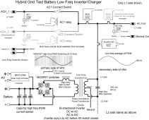
It is a bi-directional inverter. Difference between pushing out power from batteries and charging batteries is just a slight change to the MOSFET's PWM cycling.

When input AC shows up the AC_in light initially blinks. This means it has detected AC input and is adjusting inverter phasing and AC voltage to match the AC input. When it sync's to AC input the AC connect relay closes (should hear clunk of relay and LED turns solid) and inverter runs in parallel with AC input. Just slight adjustment to PWM will make inverter suck from AC input to charge battery or push out AC power from batteries.

Limiting AC input current, charging batteries, supplementing AC output (load shaving), or grid sell push, are just firmware features that tweak PWM duty cycling.,

LF hybrid inverter block diagram.png
 
Last edited:
When I say it’s dead that means it’s beyond my ability to fix. When I was poking around inside of it the very first control board labeled parallel board has a multi contact relay. I’m pretty sure that’s the problem. The breakers feeding it were labeled cb1 and cb2 L1/L2 I checked voltage at every point to that relay and there was 125v. Then it got over my head. Couldn’t find anything coming out on the printed circuit board.
 
Not sure if this helps or not,

My inverter is simular, but not exact....it is a MS4024AE......not PAE,
basically it is not load sharing and 24 volt, this is the earlier version of what became the PAE

On power up it qualifies L1 first then L2 so It will not power up on L2 alone

L1 and L2 must be 180 degrees out of phase, no two generators or two legs of three phase

When power is disconnected it reverts to factory presets if you do not have remote connected,

As a test....disconnect remote, disconnect battery to completely power down

Reconnect power after 15 minutes or so to let power capacitors discharge

Try it, mine starts and runs a 2 hp pump but this is at its maximum on start current of about 56 amps, run current 25 amps

I have 856 a.h. FLA banks of Rolls Surette with 350 MCM battery cables, under 4 feet

Magnasine wears lead shoes on service if you know what I am getting at there

I have heard that the power control relays are a weak point, but mine are original at nearly 20 y.o. now

They do not like small generators, big box style on wheels. overload capability, and frequency stability, I use a Onan 120/240 volt 6300 watt 1800 rpm generator that has windings that weigh more than a big box generator, huge rotating mass slo speed unit....430 lbs, does not like a 5000 watt Champion big box china cheepie...

lots of luck fixing it, bummer when all power is down!
 
Last edited:
Not sure if helps in your case: check the fault history. It can give you an indication about what was wrong last time. As a note, if you use AGS function and have a fault because of that, the inverter will not charge only after the fault is clear.
As a recommendation, delete the fault history.
 
According to manual MS4448PAE can accept 120vac generator input on either L1-N or L2-N connection.

AC input LED blinking means it senses AC input voltage but has not synchronized inverter to incoming AC input phase and voltage yet. This can take up to a minute depending on how far off generator frequency is. Once inverter matches phase and voltage of AC input you should hear the clunk of relay closing and LED should change from blinking to solid. When relay closes the inverter is operating in parallel with applied AC input.

Two critical things for generator input. Frequency output of generator must be within acceptance range of inverter. Spec says 50 Hz to 70 Hz for 60 Hz inverter unit. Second critical factor, that is not mentioned in manual, is stability of generator frequency. If generator is a 3600 rpm synchronous conventional generator, its engine governor rpm control must be stable and not varying engine rpms. Even solid sound with no wha-wha sound indicating unstable governor engine speed control.

Inverter phase locking and tracking is very slow with narrow bandwidth. If input frequency wobbles too much the inverter phase tracking cannot lock on and track AC input. If generator frequency wobbles more than about 0.3 Hz per second, the inverter will not achieve phase lock. Do not confuse input frequency range with frequency stability. Whatever the frequency is between the acceptable 50-70 Hz it must be stable on that frequency. This frequency stability is a common issue with synchronous 3600 rpm traditional generators that use a simple 'wind vane' governor from flywheel cooling blower.

If inverter locks onto regular grid AC input but not on generator then either generator frequency is outside of 50-70Hz or, more likely, the generator frequency stability is wobbling too much preventing inverter from locking onto AC phase.

Most 120vac only generators these days are inverter-generators, like Honda small quiet units. Inverter-generators are usually excellent for freq accuracy and stability. There are some cheapo small 120 vac only non-inverter generators. Some are even two cycle engines. These are very bad for frequency stability.

Also make sure the inverter is not set for charger standby mode. This mode shuts down inverter and just passes AC input to AC output. Also assume you have 60 Hz inverter, not running inverter at 50 Hz. operation trying to feed a 60 Hz generator to it.
 
Last edited:
Not sure if this helps or not,

My inverter is simular, but not exact....it is a MS4024AE......not PAE,
basically it is not load sharing and 24 volt, this is the earlier version of what became the PAE

On power up it qualifies L1 first then L2 so It will not power up on L2 alone

L1 and L2 must be 180 degrees out of phase, no two generators or two legs of three phase

When power is disconnected it reverts to factory presets if you do not have remote connected,

As a test....disconnect remote, disconnect battery to completely power down

Reconnect power after 15 minutes or so to let power capacitors discharge

Try it, mine starts and runs a 2 hp pump but this is at its maximum on start current of about 56 amps, run current 25 amps

I have 856 a.h. FLA banks of Rolls Surette with 350 MCM battery cables, under 4 feet

Magnasine wears lead shoes on service if you know what I am getting at there

I have heard that the power control relays are a weak point, but mine are original at nearly 20 y.o. now

They do not like small generators, big box style on wheels. overload capability, and frequency stability, I use a Onan 120/240 volt 6300 watt 1800 rpm generator that has windings that weigh more than a big box generator, huge rotating mass slo speed unit....430 lbs, does not like a 5000 watt Champion big box china cheepie...

lots of luck fixing it, bummer when all power is down!
I did both a soft and hard restart as the manual stated. But since I have to calibrate my shunt I will try your way today and see what happens.
 
Not sure if helps in your case: check the fault history. It can give you an indication about what was wrong last time. As a note, if you use AGS function and have a fault because of that, the inverter will not charge only after the fault is clear.
As a recommendation, delete the fault history.
No fault history.
 
According to manual MS4448PAE can accept 120vac generator input on either L1-N or L2-N connection.

AC input LED blinking means it senses AC input voltage but has not synchronized inverter to incoming AC input phase and voltage yet. This can take up to a minute depending on how far off generator frequency is. Once inverter matches phase and voltage of AC input you should hear the clunk of relay closing and LED should change from blinking to solid. When relay closes the inverter is operating in parallel with applied AC input.

Two critical things for generator input. Frequency output of generator must be within acceptance range of inverter. Spec says 50 Hz to 70 Hz for 60 Hz inverter unit. Second critical factor, that is not mentioned in manual, is stability of generator frequency. If generator is a 3600 rpm synchronous conventional generator, its engine governor rpm control must be stable and not varying engine rpms. Even solid sound with no wha-wha sound indicating unstable governor engine speed control.

Inverter phase locking and tracking is very slow with narrow bandwidth. If input frequency wobbles too much the inverter phase tracking cannot lock on and track AC input. If generator frequency wobbles more than about 0.3 Hz per second, the inverter will not achieve phase lock. Do not confuse input frequency range with frequency stability. Whatever the frequency is between the acceptable 50-70 Hz it must be stable on that frequency. This frequency stability is a common issue with synchronous 3600 rpm traditional generators that use a simple 'wind vane' governor from flywheel cooling blower.

If inverter locks onto regular grid AC input but not on generator then either generator frequency is outside of 50-70Hz or, more likely, the generator frequency stability is wobbling too much preventing inverter from locking onto AC phase.

Most 120vac only generators these days are inverter-generators, like Honda small quiet units. Inverter-generators are usually excellent for freq accuracy and stability. There are some cheapo small 120 vac only non-inverter generators. Some are even two cycle engines. These are very bad for frequency stability.

Also make sure the inverter is not set for charger standby mode. This mode shuts down inverter and just passes AC input to AC output. Also assume you have 60 Hz inverter, not running inverter at 50 Hz. operation trying to feed a 60 Hz generator to it.
The charger A/C in light does nothing when the generator it plugged in And the breaker is closed. That’s why the Magnum tech told me that it’s a fluke and will need to be repaired by a magnum service center.

Also both my generators are inverter type and both run at a solid 60hz so my meter claims.
 
There is also an "AC in control" setting that tells the inverter when to connect to an AC input. You can choose batt voltage, SOC, OFF, etc. Worth a quick check.
 
Hello,

I'm wondering if you have an update on your charging issue? Did you send the unit in for repair, if so, did you hear back on what the issue was?

I've been dealing with what sounds like the exact same problem - I have the same symptoms anyways. My MS4448PAE inverter/charger has been running full time for almost three years without issue. Recently the AC input (genset) charging ceased. No response at all from the charge light.

The problem first arose a couple of months ago. I had just changed the oil in a 6000W gas genset (to a slightly lighter grade than usually called for..), fired it up but no charging at the unit. Generator was putting out higher frequency (65Hz) though this is within the spec of the inverter. I tried my trusty 1000w Honda inverter generator (120) and still no charge (this generator is usually capable of charging the system on a single input leg).

On advice I brought in a brand new Onan/Cummins gas/LPG generator. Nice 240/60hz. The charging issue was gone.

Fast forward a couple of months, 30 hours on the generator, and all of a sudden the problem has returned. Absolutely no recognition from the unit that it is receiving AC power. I can trace AC all the way to the AC board, but I'm unsure of it's path from there. Magnum tech gave same advice as you - unit is faulty, needs to be sent in. Not at all convenient/practical at the moment.

No obvious damage/burns/overheating on any components inside of the unit. Inverting and all other functions work just fine. I'm trying to get access to the relay to see if this is just a stuck relay problem. Can I give power to the relay to check if it will fire? It is a Deltrol Controls 20930-81


Any thoughts on what I could check before I have to give up and send the unit away?

Thanks everyone!
No I have done nothing at this point. Luckily I designed my system pretty well and no longer need to charge off a generator. But if I do I also have the battery charger that came with my batteries. It’s only 18amps and slow has hell but it works.

Its going to be so inconvenient to send mine in for repair I don’t think I ever will unless I possibly buy another inverter. I’ve been thinking about that lately. Buying another and swapping them out then send the first in for repair then keep it as a spare. My neighbor has been living off a eu2000 for months now. His 4024PAE quit working and can’t get it fixed nor can he buy another with the supply chain issues.
 
I can survive the winter without charging batteries from the generator, but my electric needs rise heavily as the weather warms up -- too many freezers full of incoming and outgoing farm products!

My current options as I see it are:

-buy a new AC board. $500-600 and hope this solves the issue
-swap out the relay. inexpensive, but takes time waiting for the part to arrive, may not solve anything
-buy "cheap" inverter as a backup to hold me over while Magnum unit is sent off to be repaired (and who knows how long that could take, especially if they end up needing to wait for parts)
-buy a dedicated 48V charger, and live with the inverter unable to charge (I'm considering the Noco Genius GX4820)
-buy a new MS4448PAE, get the old one repaired, keep as spare or sell one of them
-buy an entirely different inverter/charger

I haven't decided what to do yet...


If I get mine repaired I'll definitely post here what the issue was found to be.
 
There is a small 120vac to 12 vac voltage sense transformer that measures AC input by the low voltage to controller board. The primary is very hair fine wire and can be blown with only slight surge current or strong ESD hit. If it is open, then inverter will not detect any AC input.

Mine blew out from a grid lightning strike to power pole in the neighborhood. After repairing sense transformer, I added a surge suppressor directly across sense transformer PCB solder pads on primary side.
got a photo to show us what part of the board you are referencing? I have the same issue with one of mine that now refuses to charge after a lightening strike. Inverter/BMK etc all works fine, just no charging.
 
Don't have pict of board but is located in AC input section near connect relay.

It is connected between AC input and connect relays so it can read AC input voltage and phase to provide info for inverter controller to synchronize to AC input before it closes connect relay putting inverter in parallel with AC input. The inverter synchronization process is time between first applying AC input and hearing the clunk of relay closing.

There are several voltage sense transformers, one on each 120vac AC input side, referenced to neutral, and possibly one across 240vac L1,L2, so it can tell if only 120vac is applied to L1 side for 120vac input only operation. When there is only 120vac applied to L1 side and nothing to L2 side it only closes the L1 relay and leaves AC input L2 side relay open.

There is also a voltage sense transformer on AC output to measure inverter output voltage when AC input is not connected. All these sense transformers are likely in same area so have to check ones on AC input side.

Firmware allows 120vac input only operation when L1 side to neutral is connected to 120vac input and no input is provided to L2 side.

If voltage sense transformer is bad the inverter will act like there is no AC input connected. If it sync's and connects then transformer is okay.

Another common problem if unit has been worked on is someone accidently reversed large power transformer L1-L2 connections. Since initial phase sync is based on open loop controller calibration, if someone reversed inverter large transformer AC output L1-L2 wires, the controller will adjust phasing of inverter MOSFET PWM drive so the inverter will have been adjusted to be 180 degrees out of phase with AC input and it will immediate pop input breaker when relay closes.
 
Back
Top