diy solar

diy solar

My DIY 60 kW 220 panel setup

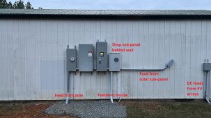
Here are some better closeups of each enclosure going left to right.

GND wires are all 1/0 Al. Everything else is 300 MCM Cu or 500 MCM Al, with the exception of the wires going through the wall in the junction box to the 200A shop sub-panels. Those are 3/0 Cu for L1, L2 and N. Oh, and the N for the solar sub-panel is 3/0 Cu as well. Those SBs don't really use N, so I figured that would be plenty.

Meter base with the new feed. Got 500 MCM L1 and L2 along with a 350 MCM Neutral coming up on the left. You can also see the #4 bare copper wire going to the ground rods. Then on the right side, is my 300 MCM L1, L2 and N leaving:
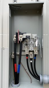
IMG_E2506.JPG

Next is the disconnect switch. This is where N and GND are bonded, both to each other as well as to the enclosure. You see the 3 cables coming from the meter base entering on the left, and you see wires existing to the right. The 2nd set of Red/Blue cables you see at the bottom is from the Solar sub-panel, the other set goes to the grid side of the transfer switch.
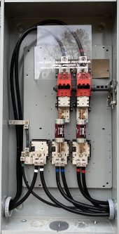
IMG_E2537.JPG

Next stop is the transfer switch. The pic below is from before I landed L1 and L2 from the solar sub-panel in the disconnect enclosure. Here you can see that GND is bonded to the enclosure as well:
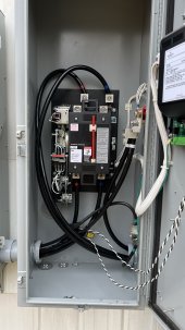
IMG_E2508.JPG

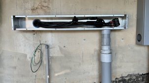
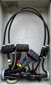
And finally, we have the "junction box":
IMG_E2536.JPG

The 4 GND wires are hiding behind the Polaris splice connector at the front bottom center. You can also see a #6 GND wire going up to ground the enclosure.

So all 4 enclosures hanging on the shop wall have their enclosures grounded. What you don't see, is that the GND wire coming from the 200A sub-panel inside the shop, is tied to the sub-panel enclose and also has a #6 bare copper going to the dual 8' ground rods.

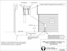
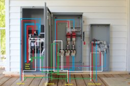
Here's an old drawing I did before installing these cabinets on my house back in 2016:
400-Trio-Wire-Layout.JPG

If you still see something I need to correct, I'm all ears. Now is the time to do it before it gets energized next week.
 
Last edited:
I think (but am not certain) that all the boxes ought to be bonded to ground by a wire rated to trip the OCP feeding power conductors in them.
Last box with Polaris doesn't appear to have that net bonded to box at all, just a small wire from ground terminal exiting bottom of box. Or maybe it goes to Polaris? But seems undersized for the job.
PVC between boxes, so no help there.

My meter panel has 200A main disconnect, and the "neutral" bus from utility is where neutral, ground rod, and ground wire all land.
Any single fault, including an open, would not electrify grounds.
Yours has similar busbar in meter panel, but only a white wire leaving it. Bonds to ground wires later.
Seems to me an open circuit in that first neutral would electrify ground downstream.

I think that meter box should have had lug for utility transformer center tap, lug for ground rod, lug for neutral of loads, lug for ground of loads. But it is one short of that.

It may be to code as you've wired it. I suggest looking at instructions for that meter box, see if you or I missed something.
 
@Hedges is right; you should have a direct bond from the utility disconnect to your grounding electrode system, preferably unspliced.
 
1.21 gigawatts!!!! 1.21 gigawatts!!!! Did you math out all the requirements yourself? That is a top shelf project. Damn you guys are geniuses when it comes to the epic projects you do. It took me over a month to grasp the realities of my 3 panel home set up, got a lot of help here. The ATS idea came from here. I think shagged a cool spreadsheet from here too. Good times.
 
@Hedges @Shimmy Below is the requirement the POCO gave me:

CVEC_grounding.jpg

The county required 2 8' ground rod spaced 4' apart, which I have at both the shop building and the house.

Ground conductors are as follows:
  • #4 bare copper looping through clamps on both rods to the new meter base
  • #6 bare copper looping through clamps on both rods to the old meter base, now being used as a junction box
  • #6 care copper double clamped to the #6 bare copper above, going to the 200A meter base grounding bar in the shop
  • 1/0 aluminum going from the grounding bar in the shop 200 meter base going to the shop junction box where is is spliced with 1/0s going to: solar sub-panel, house junction box and transfer switch
  • 1/0 going from the transfer switch to the disconnect switch
  • #6 bare copper looping through clamps on both rods at the house to the 2 200A sub-panel grounding bars
  • 1/0 coming up from the shop is spliced to 2x 3/0 copper going to the house sub-panels
Service Entrance conductors (L1 and L2) are as follows:
  • 500 MCM aluminum from transformer to meter base
  • 300 MCM copper from meter base to disconnect
  • 300 MCM copper from disconnect to transfer switch
  • 300 MCM copper from transfer switch to shop junction box
  • 3/0 copper from shop junction box to shop 200A sub-panel
  • 300 MCM copper from disconnect to shop 225A solar sub-panel
  • 500 MCM aluminum from shop junction box to 12" before house junction box
  • 300 MCM copper the last 12" to house junction box
  • 3/0 copper from house junction box to each 200A sub-panel at the house
Neutral conductors are as follows:
  • 350 MCM aluminum from transformer to meter base
  • 300 MCM copper from meter base to disconnect
  • 300 MCM copper from disconnect to transfer switch
  • 300 MCM copper from transfer switch to shop junction box
  • 3/0 copper from shop junction box to shop 200A sub-panel
  • 3/0 copper from shop junction box to shop 225A solar sub-panel
  • 500 MCM aluminum from shop junction box to 12" before house junction box
  • 300 MCM copper the last 12" to house junction box
  • 3/0 copper from house junction box to each 200A sub-panel at the house
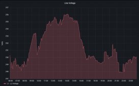
Poco came out and energized everything last week, no issues at all and my voltage rise is much less now compared to before since I now have just a single 160' run of 500 MCM to the transformer compared to 400' before with 50/50 mix of 350 and 500 MCM.

Here's the "junction box" at the house. The old abandoned meter base is on the right.

IMG_E2588.JPG

Energized "power center" at the shop:

IMG_E2584.JPG

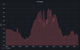
Typical voltage rise with power routed to the house first:

voltage_rise_before.jpg

So a rise of about 16 volts.

Here's what I see now that the power comes directly to the shop:

voltage_rise_after.jpg

Rise reduced by 50% to about 8 volts.

Granted the overall load on the grid plays into this as well, but the above figures are pretty consistent day to day.
 
Last edited:
Seems reasonable, except 1/0 for 200A. And is that aluminum, or copper?
2x 3/0 copper (one per 200A panel) is great.

I think there ought to be OCP sized to the utility service or 1/0 cable, preventing 400A from 2x 200A main breakers overloading it.

400A max, POCO drawing says. You have 200A meter, so they will pull suitable wire for that. Is there a breaker in the meter base?
If not, who approved 2x 200A panels fed by it? Maybe slipped past permit office?
 
Just to be clear, just the ground wiring is 1/0 aluminum or less (except the 3/0 copper going to the house sub-panels).

The L1/L2 wires are all 300 MCM copper except the last few feet going into the 200A sub-panels, where it it 3/0 copper. The 225A solar sub-panel has 300 MCM all the way to the 225A breaker.

The disconnect has 300A fuses. It came with 400A fuses since that is what its rated for, but when I presented my original plans to the permit office back in 2016 when I did the original install at the house, they had me me swap in 300A ones since I was "only" using 300 MCM cable which is rated for 320A.

The meter base I have is labeled as a 320A meter base, but the poco supplies those for all 400A services. They generally pull 350 MCM Aluminum even for 400A service, but I insisted I wanted 500 MCM, so that's what they pulled.


I found this article:

Sizing of Conductors Related to Grounding & Bonding

If references 3 tables as follows:

Minimum Size Equipment Grounding Conductors for Grounding Raceway and Equipment

According to it, #6 is sufficient for a 200A main breaker panel and #4 is good for a 300A main breaker panel.

Grounding Electrode Conductor for Alternating-Current Systems

It states that 1/0 aluminum ground is good for L1/L2 wires up to 350 MCM copper and 500 MCM aluminum. I have a mix of 300 MCM copper and 500 MCM aluminum.

Grounded Conductor, Main Bonding Jumper, System Bonding Jumper, and Supply-Side Bonding Jumper for Alternating-Current Systems

It lists the same sizes as the table above, so 1/0 aluminum for 350 Cu / 500 Al.

My site consists of the following sub-panels:

200A house sub-panel A
200A house sub-panel B
100A house sub-panel C (feed from panel B)
100A house sub-panel D (feed from panel C)
200A shop sub-panel E
225A shop sub-panel F (solar inverters)

So in theory, I can draw up to 600A from A, B and E before those breakers would flip, but the 300A fuses in the disconnect would blow long before that happened.

All my big loads add up to way less than 300A.

Main HVAC - 70A (in stage 5 heat)
7.5hp compressor 35A
car lift 30A
welder 50A

That only adds up to 185A, and the odds of those all the on at the same time are virtually nil.

The only thing that is a bit undersized I think, is the 225A breaker in my solar sub-panel. The combined wattage of my 8 SMA SBs is 55,100 Watts. @256 volts, that works out to 215A. 80% of 225A is 180A. But my arrays are not all pointing due South and not all of them are at the same tilts, so they would not all peak at the same time.
 
Last edited:
Sure, probably 1/0 aluminum OK for ground, I haven't looked up the tables.
If you have 300A fuse and 300MCM rated for 320A then sounds like everything is fine.

The following:

"1/0 coming up from the shop is spliced to 2x 3/0 copper going to the house sub-panels"

I took to mean 1/0 was the service entrance conductor, and then it appeared to be only protected downstream by the two 200A breakers (with their current summed.)
If that should be "300 MCM spliced to 2x 3/0 copper", please edit your post for posterity.
 
Late to the party. Looks great.

Would you tell me about the pipe you used for your ground mount. Rigid metal conduit? Or just 3” pipe from the steel yard? Is it 3” both vertical and horizontal? I thought the tamarack mounts has 4” vertical.

Anyway, nicely done.
 
I dropped the micro-inverters because they had a pretty high failure rate and replacing the ones on the shop roof was a huge pain. Also, I don't really have any shade issues except for that one array that sees shade in the am during summer. I think the overall efficiency is better with the string inverters as I'm running about 400 VDC as opposed to 250 VAC for the runs to the inverters.

I think I have talked myself out of adding panels to the roof on the house. The shingles there are coming up on 25 years, so I would be forced to change them out too. I'd rather put that off for a while longer. Besides, I barely have any south facing roof surface on the house.

So instead, I'm thinking I'd add a 48 ish panel array here:

View attachment 110566

Sat view:

View attachment 110567

It would be a fairly short DC run to the "power room", and they would out of view given how steep the slope is there.

Give how steep the slope there is, I'd love to go with single pole mount for each array and then have more than 2. Like maybe 4 of 12 panels each, or 6 with 8 panels each. Are there any reasonably priced single pole mounts out there?

This would be a project for next year as I've maxed out my federal tax credit for this year with the string inverter upgrade and that extra row of 15 panels on the pole barn.
Are you allowed to take the federal tax credit more than once? I want to stage my solar installation, but I have been confused by this.
 
I have taken the federal tax credit in all the years I have expanded my system, so 2017, 2018 and 2021 and will again in 2022. I don't see why you couldn't claim the credit more than once if you are staging your solar. But like Quattrohead said, you should not take the word of some stranger on the Internet.
 
Are you allowed to take the federal tax credit more than once? I want to stage my solar installation, but I have been confused by this.

Yes. Every eligible purchase in a given year can have the tax credit applied once. You can't apply the credit to the same equipment more than once.

So we bought an inverter and panels one year, batteries the next, upgraded the inverter the following year. Every year we've applied for the tax credit for solar purchases made that year.
 
The next day the POCO came out and killed the power to the house, and moved the cables from the pole into the new meter base and energized the new panel and left. It then took me about 3 hours to mount the transfer switch and run new 3/0 Cu to the sub-panels in the house. Bending 3/0 Cu is no fun at all, although it was not nearly as bad as the 300 MCM feeding the solar sub-panel.

View attachment 110474

Next I decided to pour a pad and make a "power room" where the service enters the house.

View attachment 110475

Structure done:

View attachment 110476

The roll of cable is a 24 strand fiber cable that I ran down to the shop building since I had ditch dug anyway.

20 kW Kubota generator installed and wired:

View attachment 110477

Last month I decided to ditch all the micro inverters and go 100% SMA SB string inverters. Doing all the ground mounted arrays was easy since I had easy access to the inverters, but the 56 panels on the roof were a different story.

I hauled a pallet up onto the roof, got it level, and the moved the top row of each array section onto it, and then shifted the remaining panels in each row, up one:

View attachment 110479

Inside the shop, I build a frame to hold all the inverters along with the 225A sub-panel. Here's a shot from when the shop roof arrays were still on micro inverters:

View attachment 110481

All done:

View attachment 110483

Closeup of solar sub-panel:

View attachment 110484

Getting that 300 MCM Cu cable to make the turn into the 225A breaker was a real challenge!

All PV wire going into the inverters are 10 AWG and the A/C output of the inverters going to the sub-panel is 6 AWG. The feeder wire from the solar sub-panel to the converted 400A shop meter base is 300 MCM Cu.

Output when the sun is out:

View attachment 110485

Production for the last 30 days:

View attachment 110486
Why did you dump the inverters at the pv and go with others?
 
I dumped the micros for the following reasons:

  1. High failure rates (1 or 2 per month on average out of about 140 micros)
  2. Ubiquiti no longer supports SunMax platform and software is outdated
  3. No shading to speak of on any of the arrays
  4. Voltage loss on long 240VAC runs
#1 was the main reason as it was a huge pain to replace failed inverters on the roof mounted panels. It would be a 2-3 hour ordeal (or more) to replace failed inverters in the middle of the roof, since all the panels around it would have to be removed first.
Got it. I didn’t realize that the failure rate is so high…. Even the New micros? Iq7-8?
 
Got it. I didn’t realize that the failure rate is so high…. Even the New micros? Iq7-8?
Those inverters were from a brand UBIQUITI that normally makes network equipment (ethernet switches/routers/wifi equipment) former on ubnt.com now ui.com. CEO/founder Robert Pera (used to work at apple) sometimes make projects that he thinks will make a lot of $$$ and utterly fail. They always have one thing in common: looks great, functions sub par.
Eg: they had a body wear camera that failed, they are currently doing EV chargers. Looks nice but not worth the extra $$$$
These micro inverters were one of these failed side projects. Bad bad _bad_ quality.
Can not compare to other brands like enphase, that would be insult to Enphase.
 
Back
Top