diy solar

diy solar

Need advice on my inverter / controller connections

mikek

New Member
Joined
Feb 6, 2020
Messages
11
Hi All,

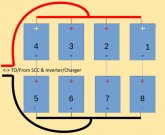
Brand new to this forum and would appreciate a little input. We installed a rudimentary solar system on the south east coast of Mexico (where sunlight is abundant 340 days a year) about 14 months ago and have noticed that our discharge rate seems coincidentally weird. I am including a diagram of our current battery setup, which is where the strange numbers occur. I am not at all concerned with our panel setup, since we are fully charged by midday on most sunny or partly cloudy days and seem to have endless energy during the day - we produce up to 5kwh per day. The batteries are all 12v 100ah and are all the same age from purchase. (We would like to add an additional 2 identical batteries into the system at this point - comments on that welcome too). We do not have access to grid power at all!

Battery Bank.png

The above diagram is our current battery setup, however we have noticed that batteries 1,3,5,7 have a higher voltage first thing in the morning (When the batteries have depleted without charge through the night) than batteries 2,4,6,8. the difference is about .5v on average, which creates a zig-zag pattern. Is this purely co-incidental? Are 2,4,6,8 slightly more worn or is this the way it should be? What do we need to do to get them to discharge evenly? I have since read that the positives for both the controller and inverter should come off the same positive pole on the same battery and the negatives off the same pole/battery on the opposite end of the bank. Is this more effective and does it make a difference? Also as a note, the batteries all read the same after a full day's charge and usage - within .08v of each other - around 13v give or take a few tenths... (P.S - the batteries are the sealed type).

Thank you kindly...
 
Last edited:
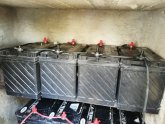
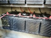
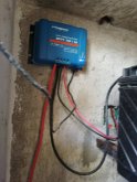
Can you post a picture of the actual batteries and wiring?
 
Have a look in here starting Page-18 https://www.victronenergy.com/upload/documents/Wiring-Unlimited-EN.pdf That should answer your question as to why they are not balancing so well.

SLA like FLA & AGM is unlike LFP / Li-Ion based batteries. as Lead batteries age they decline in capacity, sometimes one cell I a battery will be weaker that they others and that has the effect of lowering the whole battery to the "lowest common denominator" Then the lowest battery does that to the rest in the complete bank. This is just a reality of dealing with ANY lead Acid type battery. Unfortunately that means that if you want to add say 2 more which are fresh & full, they will immediately drop to the lowest common denominator within the bank itself. I run Rolls Surette S-550's (big assed deep cycle heavies) and sure enough one cell in one battery caused all sorts of havoc through the entire bank... BTDT ! Now switching to LFP.

All that said & done, there are some "tricks" for lead based systems... a PULSE CHARGER for example can help maintain a certain amount of balance and also help alleviate Sulfation Issues (happens to AGM, SLA and OpenLead) in varying degrees. There has been a LOT of argument over these, much like everything else, I have never used one but know of some that do and they swear by them.

With 12VDC batteries like you have, another option when reconfiguring to a Bus Bar system, is you can run an independent charger on each battery (like an IOTA ) and give them a "refresh" with a smaller equalisation / desulphation run (check you battery docs and follow their voltage & info), which could rejuvenate them somewhat... unfortunately, when sulfation starts there is no end to it, just keeping it from happening fast and taking good care of the batteries is all that can be done.

Make sure you battery interconnects are all the same size & length. Ensure that the connections to the NEG & POS bus are also the same length.

sla-bank.jpg
 
Thank you for the responses thus far. I would like to point out that we live in the extreme southern part of Mexico, where availability of all these gadgets is strictly by import - which is hellish expensive. If I was to import all the additional goodies mentioned, I could just as well have paid to have grid power brought to the house. The idea behind this setup is to have the most effective system, given the lack of immediate tech availability at the lowest cost.

Craig - "I would parallel them first then put in series" - the only way this is going to make sense to me is in a drawing, por favor.. I'm in no way an electrical engineer or a solar guru - this little setup is my only experience. There is a massive lack of expertise here down south, so we make do with sticks and stones really...

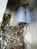
Batteries 1 - 4 Upper.jpgBatteries 5 - 8 lower.jpgController.jpginverter.jpg

Added to all this stress, there is a highly venomous scorpion the size of a man's hand running around my enclosure... Life in Mexico!
 
Last edited:
Thank you for the responses thus far. I would like to point out that we live in the extreme southern part of Mexico, where availability of all these gadgets is strictly by import - which is hellish expensive. If I was to import all the additional goodies mentioned, I could just as well have paid to have grid power brought to the house. The idea behind this setup is to have the most effective system, given the lack of immediate tech availability at the lowest cost.

Craig - "I would parallel them first then put in series" - the only way this is going to make sense to me is in a drawing, por favor.. I'm in no way an electrical engineer or a solar guru - this little setup is my only experience. There is a massive lack of expertise here down south, so we make do with sticks and stones really...
If your existing wires will reach, the most immediate thing to change that will improve your setup is to move your inverter connections to the same terminals as your charge controller (or vice versa) as @smoothJoey suggested.
 
Thank you @Bob142 and @smoothJoey I shall do that as soon as the sun goes down this evening. Easy fix that one!

@Craig Thanks for the update - If I do that then 1 - 4 and 5 - 8 batteries will have all their positives connected to positives and negatives connected to negatives as well as the top row positives connected to the bottom row negatives - however no connections between 4 and 5 - positive to positive or negative to negative - does that sound about right?
 
Just a sanity check because my eyesight is terrible.
What is the nominal voltage of the battery as a whole?
I understand from your original post that each black box is a 12 volt sealed lead acid.
 
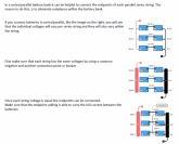
If I understand @Craig's suggestion correctly, I believe he is heading you in this direction (excerpt from page 21 of the aforementioned and linked Wiring Unlimited by Victron):
1581006803845.png
 
@smoothJoey - Yes, you are quite right, the individual batteries are 12v 100ah batteries - I was instructed to wire 4 batteries in series to maintain the 12v and add the amp hours to 400 - these two are then connected in parallel to create a 400 amp hour 24v system, which is required to feed my 24v inverter. In fact, I was given the wiring diagram by the supplier, which I followed to the T - the only change I made was to separate the inverter / controller connections to opposite ends of the bank - he had them pos and neg inverter connected one side and pos neg controller the other side..
 
@Bob142 Great, so I have it to the point of the first diagram. I would have to add the bus bars to get to the second diagram and then finally link one set of batteries to make a midpoint. I shall try and source bus bars, seems simple enough.
 
@smoothJoey - Yes, you are quite right, the individual batteries are 12v 100ah batteries - I was instructed to wire 4 batteries in series to maintain the 12v and add the amp hours to 400 - these two are then connected in parallel to create a 400 amp hour 24v system, which is required to feed my 24v inverter. In fact, I was given the wiring diagram by the supplier, which I followed to the T - the only change I made was to separate the inverter / controller connections to opposite ends of the bank - he had them pos and neg inverter connected one side and pos neg controller the other side..

4x 12 volt batteries in series is 48 volts@100 amp hours
4x 12 volt batteries in parallel is 12 volts@400 amp hours

Check the voltage at the inverter DC leads to verify the nominal system voltage.
Won't hurt to know.
 
4x 12 volt batteries in series is 48 volts@100 amp hours
4x 12 volt batteries in parallel is 12 volts@400 amp hours

Check the voltage at the inverter DC leads to verify the nominal system voltage.
Won't hurt to know.
- Currently 30v - I seemed to have confused the terminology between series and parallel - my apologies
 
- Currently 30v - I seemed to have confused the terminology between series and parallel - my apologies

That seems too high, but I have no experience with lead acid batteries.
"<snip>if you take a reading while the battery is receiving charge, it could read anything up to 14.5 volts."
soc table
 
That seems too high, but I have no experience with lead acid batteries.
"<snip>if you take a reading while the battery is receiving charge, it could read anything up to 14.5 volts."
soc table

I also thought it was a bit high, however the pool pump had just switched on as I took that reading, maybe a spike? The reading is now 27.8, which sounds a bit more reasonable. Our controller display never reads more than 28.3v on charge.
 
can you test at the battery charge and discharge leads?
I wonder if those match.
 
From the controller 28.1
To the inverter 27.8

Yep its what we figured.
Be careful with the battery and the scorpion.
If the scorpion does not yet have a name, may I suggest El Pinche.
 
Back
Top