diy solar

diy solar

One cell unbalanced - only when fully charged.

podunk5812

New Member
Joined
Mar 17, 2024
Messages
11
Location
Ohio
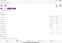
I've got a set of 4 LEV60Fs in series, Xiaoxang BMS - set to balance even when not charging. When I discharge them, the voltages match quite nicely. When I charge them, they match until a certain point, and then one is lower than the others.

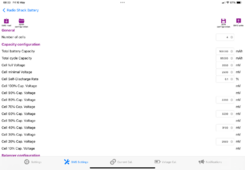
The charts below are from a full charge and they're now settling with no load attached.

1715321828707.png

Here's the overall voltage delta:

1715321849878.png


Is this something to be concerned about? This is my first DIY battery pack. Thanks in advance!
 
This is typical. Your cells are imbalanced. Voltage only relates to balance when they're nearly fully charged. Even imbalanced cells will show nearly identical voltages in the operating range.

What are your balance settings?
 
This is typical. Your cells are imbalanced. Voltage only relates to balance when they're nearly fully charged. Even imbalanced cells will show nearly identical voltages in the operating range.

What are your balance settings?

I appreciate the nearly immediate reply! I've attached screenshots of all the settings on the BMS in case any others are relevant, but first the balancer settings. The only balancer setting I changed was to turn off "balance only when charging." (I also set the capacity settings up top)


1715322874032.png


Everything else -

1715322802213.png

1715322808987.png

1715322828389.png
 
I find that these settings work for me. You may have to manually charge the low cell up to near the others to achieve proper ‘top balance’ .
Observe how the cells then track on discharge. Your settings seem fine otherwise . Also recheck the connections on the low cell terminals.
 

Attachments

  • IMG_0094.png
    IMG_0094.png
    295.2 KB · Views: 5
  • IMG_0093.png
    IMG_0093.png
    285.3 KB · Views: 5
Last edited:
The BMS you have is only capable of Passive Balancing which only burns off voltage from High Cells. Active Balancing actually moves power from Hi to Lo cells. Passive is also terribly slow due to the nature of it.

It also appears you are Over Charging past the Working Voltage Range and therefore get a runner cell that is triggering cutoffs.
Change your charging profile to a slightly more moderate settings and you'll find they will balance out nicer & easier.

Bulk / Absorb: 13.8V (Absorb for 45 minutes (3.45vpc) (some call this boost)
Equalize: OFF
Float 13.75V (3.437vpc)
MIn Volts: 10.6V (2.650vpc)
Max Volts: 14.3V (3.575vpc)
Rebulk Voltage: 12.8 (3.200vpc)

If your charging system has an EndAmp/Tailcurrent setting for changing from Bulk/Absorb to Float then set that value to 3A. When changing a 60AH Pack and the Amps taken drops to 3A it is fully saturated at that point and 100% full.

quick-voltage-chart-lfp-jpg.150247
 
It also appears you are Over Charging past the Working Voltage Range and therefore get a runner cell that is triggering cutoffs.
Change your charging profile to a slightly more moderate settings and you'll find they will balance out nicer & easier.

Thanks for the detail, I really appreciate it! This makes more sense to me. Let me put it in my own words to be sure I understand.... 3.65 is the absolute maximum a cell can be, any higher will damage it. You don't charge to that voltage, that's where the safety cutoff occurs if something goes wrong.

I don't have the solar portion of this done yet ... I was given a brand new Victron charge controller, but it's still in the box. One step at a time ;)

The charger I'm using is an iSDT Q6 nano - I bought it for the size, since this is intended to be a portable battery pack. I think the only configurable values relevant to this are the charge voltage and current. Its default for LFP is 3.65V. It does have its own balancer (is that the same as equalize?), but I'm not using it currently.

Would it be prudent to buy a higher-end charger for periodic maintenance?

And ... here's how everything is has settled so far overnight. Total delta at the moment is 31mV.

1715351521573.png

1715351572939.png
 
So interestingly, this charger (Q6 nano) can only be set as low as 3.55v. Again I don't have balance leads connected to the charger, only the BMS. I'm wondering if this charger doesn't do the absorption stuff without those leads - or at all. There's very little detail in the documentation.

I know this is a solar forum, but what chargers do people like for LFP packs in the sub-$200 range?
 
So interestingly, this charger (Q6 nano) can only be set as low as 3.55v. Again I don't have balance leads connected to the charger, only the BMS. I'm wondering if this charger doesn't do the absorption stuff without those leads - or at all. There's very little detail in the documentation.

Varies from charger to charger. I checked the manual, and it was sparse. I have dozens of iCharger models that typically cut off at 10 or 25% of the start current ("tail current" is the cut off value). The top-of-the-line iCharger 4010DUO allows you to set the tail current from 1-100% .

Since you're peak charging is at 8A, that's just barely 0.1C. When it hits full, the current will drop fast. I wouldn't expect more than MAYBE 5 minutes of absorption if that (unless your leads are high resistance).

I know this is a solar forum, but what chargers do people like for LFP packs in the sub-$200 range?

There are hundreds of options. What really matters is your goal. Most who DIY their batteries opt for a $50 0-30V/0-10A power supply. If we understood what your eventual plan is for the pack, that would help.
 
Varies from charger to charger. I checked the manual, and it was sparse. I have dozens of iCharger models that typically cut off at 10 or 25% of the start current ("tail current" is the cut off value). The top-of-the-line iCharger 4010DUO allows you to set the tail current from 1-100% .

Since you're peak charging is at 8A, that's just barely 0.1C. When it hits full, the current will drop fast. I wouldn't expect more than MAYBE 5 minutes of absorption if that (unless your leads are high resistance).


There are hundreds of options. What really matters is your goal. Most who DIY their batteries opt for a $50 0-30V/0-10A power supply. If we understood what your eventual plan is for the pack, that would help.


Thanks for the detailed explanation. I do have a quality bench power supply, I’ll try that out, I assume I just want to set the voltage to where it needs to be (13.8?) and then set a reasonable current limit according to what the cells can handle?

This battery pack will be used primarily for portable amateur radio operations. So… maybe .5-1 amp continuous with short bursts of maybe 10-12 amps for a minute or so at a time. Relatively low duty cycle. 74ah might be a little overkill, but we have operating events where we operate “off-grid” for 24 hours.

So yes eventually a solar charge controller is going to go on there to keep it topped off, but primarily I’ll likely be charging from the grid, and my main goal is longevity - I’d like to not cook the cells early!

Right now I’m mostly concerned with learning about building these packs, charging and maintaining them, etc - and you guys have been really helpful!
 
Thanks for the detailed explanation. I do have a quality bench power supply, I’ll try that out, I assume I just want to set the voltage to where it needs to be (13.8?) and then set a reasonable current limit according to what the cells can handle?

Simply charge each cell individually to 3.5V @ 10A. Make sure you use quality leads with a good connection. Alligator clips will have a massive voltage drop.

This battery pack will be used primarily for portable amateur radio operations. So… maybe .5-1 amp continuous with short bursts of maybe 10-12 amps for a minute or so at a time. Relatively low duty cycle. 74ah might be a little overkill, but we have operating events where we operate “off-grid” for 24 hours.

Then the question becomes how fast do you want to charge it?

Don't get hung up on "LFP" specific chargers. Almost any 12V charger can work with some limitations. In fact, you already have two chargers that will work.

Personally, I'd fashion a second harness and get the balance leads hooked up to the Q6 and be done with it. :)
 
Awesome. Thank you. One more thing - what type of connector is used in that Q6? Not sure if you know or can tell by looking. I likely have the right crimp tool but don’t know what connector to order.
 
Awesome. Thank you. One more thing - what type of connector is used in that Q6? Not sure if you know or can tell by looking. I likely have the right crimp tool but don’t know what connector to order.

RC chargers typically use JST-XH:


I like to get these extension cables, cut the female end off one, and crimp on the ring terminals. Then I can chain them together if I need more length to the balance leads.
 
One other question - I assume it's generally safe to connect two sets of balancing leads to the cells? e.g. the harness for the BMS and the one for the charger? Or is it best practice to disconnect one when connecting the other?
 
One other question - I assume it's generally safe to connect two sets of balancing leads to the cells? e.g. the harness for the BMS and the one for the charger? Or is it best practice to disconnect one when connecting the other?

Separate set of leads is absolutely fine. Where you run into problems is trying to use ONE set of leads for two devices... several folks have tried that with disappointing results. Most common is to try to tap into existing leads with an active balancer. The thin BMS wires add notable resistance when active balancers are moving current. The active balancing BMSs compensate for this, but the passive balance BMSs just see notable voltage fluctuations and can trigger over and under voltage protection just from current on the balance wires.

I personally have an 8S LFP connected to a JBD BMS with a separate set of balance leads for balance charging. Works great.
 
I want to be absolutely sure I'm wiring my balance leads correctly, so I drew a shitty diagram of how I think they should be connected. Again this is a 4S pack.

In the diagram, the holes of the connector are facing downward, the wires upward, and the connector is oriented so the little guide tabs are down.

Is this the right way to wire this?

1715571888865.png
 
I honestly have to triple check it each and every time, and my chargers only have pins with no guide wires, so I have to manually get it right each time.

The extension wires I linked should be correct with the red at the most (+) position. Then it's up to you to only wire the first 5 black wires from the other end.

Yup, that's the case. And it turns out my diagram was correct, the charger shows voltages for each cell that match my measurements. Again, appreciate the help.
 
Back
Top