diy solar

diy solar

Optimal settings for Victron MPPT

DerBuchner

New Member
Joined
Oct 5, 2022
Messages
24
(background: currently I have 2 x Hoymiles HM-1500 and 8 x panels (415 Watt each))

I would like to build a DIY LiFePO4 with 48V and charge it with a Victron SmartSolar MPPT 150/35 (edit: forgot to mention: I have two of those).

I assume thousands have done exactly the same before :) ... so there should be some kind of optimal configuration.

Question: Is there on this forum (or elsewhere on the web) an optimal configuration for the Victron MPPT?
 
Last edited:
Assume you're removing the HM-1500.

There is no optimal configuration and brand doesn't matter.

Victron MPPT are rated in OUTPUT current with separate input current limits.

8 * 415W = 3,320W

3320W / 55.2V ("average" charge voltage) = 60.1A

A 150/35 would only be able to use 55.2V * 35A = 1,932W maximum (2000W maximum per spec)

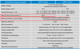
If it was your intent to overpanel the controller by >50%, that's what you've done, and that's fine provided you haven't exceeded any parameters:


1677759723255.png

1a) If more PV power is connected, the controller will limit input power.
1b) The PV voltage must exceed Vbat + 5 V for the controller to start. Thereafter the minimum PV voltage is Vbat + 1 V.
2) A PV array with a higher short circuit current may damage the controller

You need to leave at least 10-15% overhead on panel series Voc to ensure you don't exceed 150V in cold temps. Your panel should have a temperature Voc temperature coefficient.

Absorption:
Fast charge: 3.55-3.60V/cell, 30 minute fixed absorption, .05C tail current.
Slow charge: 3.45V/cell, 2 hr absorption, 0.02C tail current.

Slow charge is believed to potentially improve cycle life by charging at lower peak voltage/current but still attaining 98%+ SoC. It may also be more advantageous for allowing more time for the BMS to maintain top balance.

Float: 3.375V/cell

If charging below freezing is a risk, you either need a BMS capable of low temp charge protection or you need to provide provisions for heating the battery.
 
Assume you're removing the HM-1500.
Yes.

A 150/35 would only be able to use 55.2V * 35A = 1,932W maximum (2000W maximum per spec)
I have 2 of those (sorry, should have made this clear in the first post).

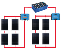
My panel configuration will be 2s2p per MPPT, so like this:
1678030359571.png
Because of the parallel connection: do I have to add bypass diodes or fuses somewhere in front of the panels?
 
Because of the parallel connection: do I have to add bypass diodes or fuses somewhere in front of the panels?

Only if you have extreme partial shading potential, i.e., where one string might be completely blacked out while the other is in full sun.

You don't need fuses or breakers when your array is single string or 2P, but you can if you want.

EDIT: BYPASS diodes are in the panels. In my head, I read blocking diodes.
 
Last edited:
You are going from 4 MPPT with two panels each to 2 MPPT with 4 panels each. I assume your shading is normal and not crazy? If it’s normal the 2 MPPT would probably be fine.
 
Only if you have extreme partial shading potential, i.e., where one string might be completely blacked out while the other is in full sun.

You don't need fuses or breakers when your array is single string or 2P, but you can if you want.

Unfortunately I do have some shading. The panels are on my garage and in the afternoon shading from my house comes in.

Where would I have to place bypass diodes in my setup?
 
You already should have bypass diodes in the panels. You probably want to try blocking diodes. I don’t believe those are generally used these days.

You might pull off the panel level data your HM1500 sent to the DTU if you want to guesstimate what the MPPT change will do for you.
 
After some research I found out that I don't need blocking diodes.

1) IEC 61730: This standard requires a reverse current test (reverse current through the module of 135% of the specified max. overcurrent protection for 2 hours). Most modern panels (also mine) support this standard.

2) maximum reverse current = (number of strings - 1) x module short-circuit current.

Because I have only 2 strings in parallel I'm fine :cool:
 
Yeah to some extent talking about blocking diodes is a bit like unfreezing a solar caveman from 2000 or whenever they were standard.

And you’ve seen there why 2p is less of a PITA than more p
 
Back
Top