diy solar

diy solar

Panel grounding to rod at location (not to main breaker due to distance)

The structure is just an auxiliary grounding rod according to NEC.

I think some believe an EGC from array to main system grounding is not needed as there is a ground rod at the array. Any grounding at the array is just an auxiliary ground. It is required to connect it to main grounding system.


When it comes to grounding, it would be wise to follow it. I think some like to interpret certain sections or choose a menu of only certain things. When it comes to grounding, it is quite specific.


As long as there is a grounding electrode at the main panel with N-G bonded and an EGC that runs with current carrying conductors from the PV array, then it is according to NEC grounding requirements. Anything else is fluff and not needed or required, in other words, money down the toilet.

Many believe they can use either a grounding electrode or the array structure as the grounding for the array. This is incorrect, any grounding at the array is an auxiliary ground. An EGC needs to be run from array/auxiliary ground to main grounding system which is usually at the inverter/electrical panel installation. An auxiliary ground is not needed, nor is it not permitted. It just "exists".

What NEC should do is to not allow an auxiliary grounding electrode, it would eliminate confusion. A metal PV array structure is allowed but not an auxiliary grounding electrode.
For those that have a wooden array structure and do not want to run a ground wire back to the mains because of distance what would be the best way to simulate a metal pv array structure to eliminate the problem??

Bolt a metal plate to one leg of the wooden mount at the bottom and run a cable from the arrays frames to it? Were just talking about eliminating the equivalent of static discharge like you built up sliding off a truck seat getting out right? Well except it never ends :)

For the record I don't know that I even have this problem but I figure why not eliminate it now just in case :)
 
When it comes to grounding, it would be wise to follow it. I think some like to interpret certain sections or choose a menu of only certain things. When it comes to grounding, it is quite specific.
I think this is wise in the NEC territory. And probably CEC territory since it's somewhat close, and if your option is zero educational materials or NEC based educational materials, might as well use NEC which is probably 80% right for north of the border instead of YOLO'ing with a 0% understanding.

Now outside those territories it's probably best practice to conform to local standards just so if other people need to work on the system, there are no surprises.
 
For those that have a wooden array structure and do not want to run a ground wire back to the mains because of distance what would be the best way to simulate a metal pv array structure to eliminate the problem??

If the electrical systems are connected then you have to run an EGC back anyway.

If the electrical systems are disconnected then many structures will need to be grounded to the same standards as say a home. Bond main panel through GEC down to appropriately sized ground rods / those foundations that have grounding designed into it, etc. Bond N-G in main panel. Basically, what you would do if you were feeding that building with a generator, or preparing the building to be connected to the grid. IE a very standard workflow for GCs and electrical contractors, no reinventing the wheel for solar needed. And then bond the array's metal parts to it.
 
For those that have a wooden array structure and do not want to run a ground wire back to the mains because of distance what would be the best way to simulate a metal pv array structure to eliminate the problem??

Whoa. It is required to run an EGC with any current carrying conductors.

If you don't run any current carrying conductors, then you don't need an EGC. :ROFLMAO:

I don't know where the idea came from that an EGC is not required to be run from an array to the main system grounding system. If it can carry current, such as metal, it has to have an EGC and an EGC has been required to run with current carrying conductors.

This is for ground fault clearing to prevent electrical shock.

Any grounding done at the array that is a grounding rod or structure is not a proper ground system that meets the requirements of NEC. If it has current carrying conductors, it requires an EGC. If it has a metal frame, enclosure, etc that could carry current should a short occur, it requires an EGC.


Bolt a metal plate to one leg of the wooden mount at the bottom and run a cable from the arrays frames to it? Were just talking about eliminating the equivalent of static discharge like you built up sliding off a truck seat getting out right? Well except it never ends :)
Not needed. The EGC has to be run from the array with the current carrying conductors to the main grounding system. The EGC will be at zero potential and dissipate any static charge.

For the record I don't know that I even have this problem but I figure why not eliminate it now just in case :)
You need an EGC to run from the array to the main grounding system.

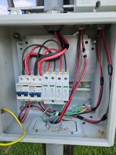
On my array, I have SPD's and those are connected to the EGC. That should help with dissipation due to a nearby lightning strike. A direct strike forget it, things probably get fried. Note the green EGC is ran into the conduit at the bottom. This runs with the current carrying conductors to the house.


PV array box inside.jpg
 
Is the EGC required to run parallel to the CCC in an ungrounded PV system? It will quite rarely be used/effective in clearing faults, but it will be used in detecting faults by giving the ground fault detector a chance to trigger.

EDIT: in the specific case of your setup, suppose there is a ground fault at 6:30AM. None of those breakers are going to have enough current to trip with such low solar output.

(It will still do the duty of providing a path back to GEC for dissipating voltage due to static or AC coupling of an ungrounded AC generator to ground).
 
Whoa. It is required to run an EGC with any current carrying conductors.

If you don't run any current carrying conductors, then you don't need an EGC. :ROFLMAO:

I don't know where the idea came from that an EGC is not required to be run from an array to the main system grounding system. If it can carry current, such as metal, it has to have an EGC and an EGC has been required to run with current carrying conductors.

This is for ground fault clearing to prevent electrical shock.

Any grounding done at the array that is a grounding rod or structure is not a proper ground system that meets the requirements of NEC. If it has current carrying conductors, it requires an EGC. If it has a metal frame, enclosure, etc that could carry current should a short occur, it requires an EGC.


Not needed. The EGC has to be run from the array with the current carrying conductors to the main grounding system. The EGC will be at zero potential and dissipate any static charge.


You need an EGC to run from the array to the main grounding system.

On my array, I have SPD's and those are connected to the EGC. That should help with dissipation due to a nearby lightning strike. A direct strike forget it, things probably get fried. Note the green EGC is ran into the conduit at the bottom. This runs with the current carrying conductors to the house.


View attachment 160926
What does the yellow wire go to?
 
This may be a case of using the right verbiage so people can understand. The panels and combiner box are all grounded at the main grounding rod. The grounding wires run through the same conduit back to the main rod. And in the case of an off grid panel they would still have one specific ground.
 
My whole array is metal and grounded by the EGC.
The pipe coming up into the box is from the house right?

I'm trying to understand the wire size and how they go thru the breakers is why I'm asking.

I'm guessing there are more boxes involved in all of this at the array than just the one shown.
 
Ok never mind I get it now looking at the post you made on the installing the mount.
 
@sunshine_eggo has a link in his sig about grounding from the NEC. Watch it. Basically it says everything above the earth ties to a single point to everything below the earth. The key takeaway is you only want one path from above the earth to below the earth, the video explains why.
 
Ok never mind I get it now looking at the post you made on the installing the mount.
Any questions just ask, it is best you understand why it is done this way.

Even though my whole array has a metal mount and the metal poles are encased in concrete over 8 feet deep, it is not considered to have proper ground. It is only when an EGC is ran from the main grounding system and connected to the array that it meets the requirements.

The purpose is that if the whole array was energized by AC power it would create a ground fault and current would return to source on the EGC to trip a breaker. The earth is a poor conductor, we want a low impedance path back to source.
 
Mike Holt explains what is required concerning the EGC under NEC at this point in the video. Later on, he explains that any other grounding electrode is an auxiliary ground that is allowed to be installed but not required.
 
  • Like
Reactions: JRH
Any questions just ask, it is best you understand why it is done this way.

Even though my whole array has a metal mount and the metal poles are encased in concrete over 8 feet deep, it is not considered to have proper ground. It is only when an EGC is ran from the main grounding system and connected to the array that it meets the requirements.

The purpose is that if the whole array was energized by AC power it would create a ground fault and current would return to source on the EGC to trip a breaker. The earth is a poor conductor, we want a low impedance path back to source.
Well the problem I still have is how the ac is getting into the panel frames. I don't think I have the issue myself but others do.

Since the dc cables and dc solar cells are isolated from the frame of the panels then grounding those frames to avoid the weird static ac buildup people are experiencing at the panels themselves makes far more sense to me than running a ground wire back to the house for it.

There is no loop circuit being completed from the house with this weird effect. I fully understand it being needed if the ac was connected to the panel frames or even the dc and it going along the dc wires since ac can piggy back like that. But there isn't supposed to be a direct connection from those dc wires to the frames.

So if its just occurring at the panels and not a loop then grounding the frames at the array makes more sense. It would be like grounding the neighbors ac back to my ground point. Sure it would work but it wouldn't make much sense.
 
Capacitance would be my guess. If you put AC on your PV line (Which still seems odd to me, sounds like a grounding issue in the inverter, with the PV lines) and the other end of that AC has an earth ground and you have an insulator between the frame and the PV wires you just created a capacitor albeit a crappy one between the AC on the PV wire mesh and the frame. DMM is going to measure the voltage drop, so if the internal resistance of the meter is similar to the reluctance of the AC circuit you created with the crummy capacitor, you will read roughly 1/2 the voltage, as you have created a simple voltage divider with your meter and the capacitor.

Again, just a guess. Feel free to shoot it down.
 
Is there a AC circuit leading back to the house? If not all the discussion around bonding back to your house goes away. Nobody will complain about potential deviation from code if you have isolated system and then bond solar module frames to main panel in isolated building then bond main panel to grounding electrode via GEC. Or bond panels to grounding electrode via a GEC connection instead of sharing the EGC.

I don’t think you provided an authoritative system diagram so it’s hard to tease one out by gathering info from a bunch of text posts. You are supposed to run an EGC with either AC or DC wiring. And the EGC is relied on by the safety components. Clearing faults for AC and ground fault detection device for DC (to detect stray voltage on the frames and other stuff).

As for how the AC gets on the frame/in the DC lines. That is an interesting question but it’s not necessary to root cause before proceeding with correcting your grounding. it’s clear from user reports AC on DC lines (I assume it is because of non-isolated inverter topology) can make it onto the frames even though they are isolated to an extent from the PV cells. Since this is probably weak capacitive coupling the panels, the GEC/EGC to proper ground rod bond should overpower it.
 
Last edited:

In this video Grady has an example of how even an isolated ungrounded transmission line will have a meaningful (needs to be analyzed for insulator voltage breakdown) and measurable voltage to ground. He says it is from shitty capacitor forming in the air/other dielectrics in the environment.

He also has an example of how a ground fault will shift the voltages induced by that. By extension we can presume that the intentionally induced grounding of the panel frame will also be capable of shifting the voltages.
 
For the weak capacitively coupled AC (or however else it is getting there) the separate ground (worst case installation mistake — not bonded to MSP in your detached building) will probably be sufficient to overpower it.

For AC that gets on panel from ground fault (maybe there’s a short inside the inverter combined with a short from DC to frame directly. Fault implies some deviation from how things are supposed to work). The worst case of no MSP bond means that this AC happily stays on the frame, and the ground rod also gets pulled up to this AC voltage. If there’s wet ground over there the ground will also get pulled up.
 
Back
Top