diy solar

diy solar

Pylontech 8 x US5000 wired into 2 x Lynx Distributors -- Would this work?

AlaskanNoob

Solar Enthusiast
Joined
Feb 20, 2021
Messages
967
Apparently the cables supplied by Pylontech for their batteries are only rated for about 100 amp and the terminal connectors for about 130amp.

I'm going to have 400 amp going into the batteries from the Lynx Distributors for charging (2 SCCs that put out 200 amp each).

Apparently a solution to the Pylontech cable limit of 100 amps is "doubling up" the wires. I'm trying to figure out how to double up the wires.

Would that mean:

AB to 3
EF to 4
GH to 5
CD to 6
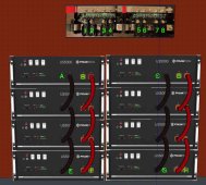
pylontech wiring.jpgWould that work? Since the power from the Lynx will split between two stacks of four batteries, I would assume that would be 200 amp going into each stack of 4 batteries. So if I double the 100 amp wires, I think I'd be good but I just want to confirm.

If so, then I'd have the two inverters wired into 2 and 7, and the charge controllers wired into 1 and 8. From looking at the Victron Wiring guide, it seems to suggest wiring up the batteries into the middle of the Lynx. I guess for more even power distribution.

Many thanks for the assist!
 
Don't get the lynx distributor for aggregating the batteries.
Use 2x lynx power-in instead because the batteries should be fused at source.
You can then attach lynx distributors for the rest of the system.

The lynx products have a positive and negative bus bar.
A goes to 1 positive
B goes to 1 negative
rinse and repeat.
Thanks for that. I've heard others argue for what you're suggesting, although I think I've seen wiring diagrams where it's done like this with the distributors although I may have mis-read them.

Is the issue with using a lynx distributor for aggregating the batteries that the fuses in the lynx distributor are too far from the batteries? Or is it because if the fuse blows in the lynx distributor, the power from the batteries will flow along the bus bar to other fuses?

That issue aside, would the wiring/cable rating issue be solved with the wiring I asked about?
 
The difference between the power-in and the distributer is the
Is the issue with using a lynx distributor for aggregating the batteries that the fuses in the lynx distributor are too far from the batteries?
Yes.
You want the fuses as close as possible to the battery positive terminal to minimize the chance of an upstream short.
That issue aside, would the wiring/cable rating issue be solved with the wiring I asked about?
Yes, in the topology I suggest each battery, battery wire and battery fuse only sees 1/8th of the total current.
 
You want the fuses as close as possible to the battery positive terminal to minimize the chance of an upstream short.

Yes, in the topology I suggest each battery, battery wire and battery fuse only sees 1/8th of the total current.

I think I get the upstream short thing. Maybe not. But looking at the diagram the way I had it I was wondering if a set of battery wires blew the fuse, why wouldn't the power try to travel through some other fuses on the bus bar to re-complete the circuit (which I would assume would be more current overloading other fuses on the same bus bar and blowing them). I'm not sure if I'm understanding that correctly, but either way it sounds like I need to switch to the power in. And then buy some fuses for the batteries. So that way if those fuses pop, the power can't flow to the bus bar and try to go through other fuses.

If I'm thinking about that somewhat correctly, that turns on a lightbulb for me. Much appreciated.

If it is going to cut the current in 8 by going that route, that would mean all my battery wires would only have to be able to handle 50 amp is that right? That's awesome if that's the case since then I wouldn't have to double up wires.

Very much appreciate the education!
 
I think I get the upstream short thing. Maybe not. But looking at the diagram the way I had it I was wondering if a set of battery wires blew the fuse, why wouldn't the power try to travel through some other fuses on the bus bar to re-complete the circuit (which I would assume would be more current overloading other fuses on the same bus bar and blowing them).
Your drawing makes no sense.
Please implement my suggestion.
I wonder if you understand my suggestion.

My design isolates faults to a single battery.
 
You have 8 batteries.
Each goes to own its own terminal pair on the power-in
 
Your drawing makes no sense.
Please implement my suggestion.
I wonder if you understand my suggestion.

My design isolates faults to a single battery.
You have 8 batteries.
Each goes to own its own terminal pair on the power-in

I thought I understood your suggestion, but apparently you're right, I don't.

You're saying 8 long sets of wires from every single individual battery to 2 x Lynx Power In modules and 8 fuses before going into the power in modules?

Why wouldn't I just wire the battery bank in parallel as I planned and cut down the wires going into the Lynx Power in module?
 
I thought I understood your suggestion, but apparently you're right, I don't.

You're saying 8 long sets of wires from every single individual battery to 2 x Lynx Power In modules and 8 fuses before going into the power in modules?
Yes
Why wouldn't I just wire the battery bank in parallel as I planned and cut down the wires going into the Lynx Power in module?
Many reasons.
1 Fault isolation.
2 Keep the current low to each battery
3 Keep the current balanced over all the batteries
4 extensibility and ease of maintenance

I'm sure I could think of more if I wasn't distracted.
 
Yes

Many reasons.
1 Fault isolation.
2 Keep the current low to each battery
3 Keep the current balanced over all the batteries
4 extensibility and ease of maintenance

I'm sure I could think of more if I wasn't distracted.
These "smart" batteries all talk to each other and to the Victron charge controllers so wouldn't the battery BMS themselves or the Victron equipment keep the current balanced over all the batteries? I would hope the BMS and Victron interacting and communicating with the smart batteries would also be able to aid in fault isolation but I don't know if they do. Either way, if a blown fuse isolates half the batteries rather than one, I'd be fine with that.

I haven't seen anybody wire up all eight batteries individually like that especially in a server rack battery setup. What you're proposing adds a lot of copper, makes the current lower than it needs to be which I suppose is a plus in some ways, but it's not needed. I don't think your solution adds anything to current being balanced with smart batteries and I think any benefit for ease of maintenance would be minimal especially with all this added wiring your solution throws into the mix.

But I do think the Power In Lynx and fuses between the batteries and the Lynx Bus Bar is probably a good idea. Thanks for that.
 
Last edited:
These "smart" batteries all talk to each other and to the Victron charge controllers so wouldn't the battery BMS themselves or the Victron equipment keep the current balanced over all the batteries?
Even if they could which I doubt, they would be fighting a bad topology.
I'm going to stop trying to force feed you now.
 
Last edited:
While Joey disagrees, it appears to me my setup will work. The Victron documentation says the Lynx DC Distributor (which has fuses) can take power from batteries. If a Lynx Power In is used instead (no fuses) then all the positive power needs to be fused before it gets to the Lynx Power In bus bar.

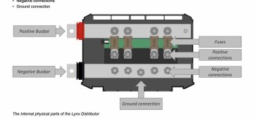
So using the Lynx DC Distributor with fuses means if a battery or set of batteries wired in blows the fuse, it will not be connected to the bus bar and will not try to go through other fuses on the bus bar. This graphic shows it:

lynx bus bar.jpg


This solution does everything Joey was talking about although it would appear he would want more Lynx DC Distributors so that each individual battery would be wired to its own port which is another issue.

I still need to figure out the double wiring though. What would happen if EF blew the fuse in Port 4? Would AB still supply power to Port 3? Or would the assumption be (this is my guess) that the current that blew the fuse would be split evenly between AB and EF and so if one blew, they would both blow? That's my guess but I need to look more into it. I would likely need to ensure the cables from EF and the cables from AB were the same length rather than as depicted in the picture, of course.
 

Attachments

  • double wire 1.jpg
    double wire 1.jpg
    100.2 KB · Views: 22
Last edited:
While Joey disagrees, it appears to me my setup will work. The Victron documentation says the Lynx DC Distributor (which has fuses) can take power from batteries. If a Lynx Power In is used instead (no fuses) then all the positive power needs to be fused before it gets to the Lynx Power In bus bar.

So using the Lynx DC Distributor with fuses means if a battery or set of batteries wired in blows the fuse, it will not be connected to the bus bar and will not try to go through other fuses on the bus bar. This graphic shows it:

View attachment 83925


This solution does everything Joey was talking about although it would appear he would want more Lynx DC Distributors so that each individual battery would be wired to its own port which is another issue.

I still need to figure out the double wiring though. What would happen if EF blew the fuse in Port 4? Would AB still supply power to Port 3? Or would the assumption be (this is my guess) that the current that blew the fuse would be split evenly between AB and EF and so if one blew, they would both blow? That's my guess but I need to look more into it. I would likely need to ensure the cables from EF and the cables from AB were the same length rather than as depicted in the picture, of course.
This image illustrates the communication and wiring to create 2 battery banks. You could also have turned this into 8 separate banks as was discussed. The comunication wiring remains the same. Here's the link to the topic at Victron: https://www.victronenergy.com/live/battery_compatibility:pylontech_phantom#example_wiring_diagram
Look also at the pdf from Victron Energy on their website titled "wiring unlimited" and search "lynx" to
 

Attachments

  • ds_-_pylontech_-_managed_lithium_battery_-_2021-3-11.jpg
    ds_-_pylontech_-_managed_lithium_battery_-_2021-3-11.jpg
    80.2 KB · Views: 14
I hit post tooo early... wiring unlimited page 27 illustrates the correct lynx device order.
 
These "smart" batteries all talk to each other and to the Victron charge controllers so wouldn't the battery BMS themselves or the Victron equipment keep the current balanced over all the batteries?
That's just not physically possible with the topology of 99.9% of BMSs out there. They can totally stop current. But they can't make minor adjustments.
But I do think the Power In Lynx and fuses between the batteries and the Lynx Bus Bar is probably a good idea. Thanks for that.
I'm not super familiar with Pylontech, but a quick googling reveals they have built in fuses. "dual passive and active fuses" I'm not 100% sure what that marketing speak means, I've never heard of active or passive fuses. But fuses do fuse things. You don't need fuses on both ends of the wire from the battery to distribution/bus bar thing.


Your idea, with a minor adjustment, would work. The center 4 batteries would see less load when compared to the top and bottom in each stack.

*I think you already figured it out, but the positive and negative in those Victron distribution boxes stack on top of each other. So A and B would go to 1, C and D would go to 2, etc.


Dang it, I fell for the old "someone replied to an ancient post" thing ?
Oh well...
 
Back
Top