diy solar

diy solar

Simple home made analog MPPT contoller

Buck converters can be made to be very efficient, but only if the voltage step down ratio is fairly low, say 2:1 or 3:1
"Scaling up in current is much more practical and easier to do than scaling up in voltage."

I was planing on having the 9 & 8 panel's as a mix of series & parallel, using the panel spec's the 9 mix (3 in parallel as 3 in series) = 114v 39A.
But it sounds like least is best, 3 in series only is ok, though in aiming for a sweet spot in cable use
3 strings (2 of 6 panels + 1 of 5 panels) would be nice, if realistic for your design on the 17 panels?

Ok, so if the panels likely spec's are ~332W, 38V, 11A, & if 17 panels in 3 strings is ok?
then for the 6 stringed panels what would be best

(3 in series as 2 groups in parallel) =1992W/96V
= ~21A
or (6 in series) = 1992W/192V =10A
(192v on a tin roof & a bit >3:1 buck)

The odd # 5 panels is tough & can only be in series = 1660W/160v = 11A
for the buck that's a 3:1

I hope my numbers add up.

So which combo, if any, of the above are suitable?

Next step will be the Gerber file, no problem if you don't have a copy?
I can draw it up & make it available to any body who may want to use it, if that's ok?
Once I've done that I should be able to run simulation test's, I've found a number of online sites for this & they can make the PCB, & even add the electronic parts, although I'll probably add the mosfet's, capacitor's & chokes etc, I like the easy mosfets replacement option in your design, plus it keeps it small & light for post.

As I say this is all knew to me, its a real learning curve, so let me know if I'm mistaken in any of the above. All in all a fun project.
 
It all sounds quite reasonable and doable.

I suggest first thing might be to build up a very simple working prototype, there are very few components in the control system.
That should be possible without making an actual circuit board, and it will give you something to experiment with and gain confidence and experience.
A single string of three panels to begin with, and work up from there.
 
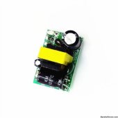
a dc input voltage of from typically around 30 to 35 volts
Just wanted to be sure before ordering, your link & others on ebay.com have them rated as "Input voltage: AC 85 ~ 265 v 50/60 hz or DC 100~ 370 v."

Does that mean my input has to be >100V?
( just got a tin/cu 6mm x 100m roll of solar cable, so got plenty & I should be able to do series of 3 x 38v pv's ~(1404 w), but you reckoned it's more like
32v x 3 = 96v
Also with 17 panels means 1 series of 2 panels = 64v input.
If needed I can do larger series combination's, but trying to keep the watts as close to yours as possible.aaas-l1600.jpg
 
Last edited:
I've yet to build this SCC but have bought the components. My original order for these power supplies got lost but then turned up after 6 months! Anyway, I tested on the bench and they turn on ~70V so 2 panels in series is ok.
 
Does that mean my input has to be >100V?
The specifications DO say 100v dc minimum, but that probably only applies if you need to draw the full maximum of 450mA rated power output.

Under no load, or extremely light load (as we will be running them) all the supplies I have bought from China so far, from several different sources over a few years, typically all started up at about 35v to 45v. Others over at The Back Shed have had a similar experience.
Once running, the dc input voltage can fall much lower than the start up voltage, and the supply keeps on running.

@Ellcon123
That is a real surprise that you need 70v !
If that is a concern, I suggest you order a few more from a different supplier, they are dirt cheap.
At this stage you can probably use what you already have to do some testing.
 
Last edited:
At sunrise when the whole thing wakes up, solar panel voltage will rise up from zero, but with the solar controller powered down until it reaches the start up threshold voltage.
So it always starts off initially with full open circuit no load panel voltage, which you will always get.
 
My panels are all wired 2s and that's how they will stay. Panels are 38Voc and definitely didn't power up on 1 but 2 was ok.
 
See how it goes.
But I would still try to source some different power supply boards.
These are produced by the millions for dc wall packs in every different country around the world.
Many different Chinese companies make these small supply boards, and they do have very slight changes in behavior between batches.
Only thing that is very rigidly kept the same are the external board dimensions, to fit into the standard plastic housings everyone uses.
Its very likely the small ferrite flyback transformer has slightly different turns, turns ratio or air gap from different board manufacturers.
 
Last edited:
small supply boards, and they do have very slight changes in behavior between batches.
I recently ordered a batch (alibaba) huge variation in component ratings, but all have the same spec's.

I'm using EasyEDA for the PCB & probably the parts, (its cheaper than buying a breadboard, its also a really good learning aid, & I can run simulations on the design there, & the PCB design is stored for anyone to use).

Q?. So I started with the TL494 21.6KHz PWM controller.
Searched through their available parts list (many to chose from, & all look different, 15 cents - 95 cents each).
(Texus instruments has >~ 16 TL494, same # of pins etc).

But it is listed as 300KHz, your plan lists it at 21.6KHz.
So your resistor R7 (external timing resistor)
on the RT6 pin determines the value of 21.6KHz?

So am I right in thinking I can use any of the TL494 available?

If I'm wrong, what's the make etc you have used?


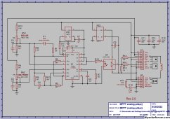
Analog MPPT circuit dia.jpg

Just a note for other readers be sure to search/read the pdf data Texas instruments TL494.
 
Hi Sunwalker.
I sometimes tend to put little cryptic messages on my circuit diagrams to show voltages, frequencies and such.
It sometimes helps to understand how the circuit works, and what to expect when measuring at a certain pin or component.

R7 (R timing) and C4 (C timing) set the operating frequency, which with the values given gave 21.6Khz on my prototype board.
Its not in the least critical, anything around 20Khz to 25Khz will work just fine and the frequency will vary a bit from chip to chip anyway.

The TL494 chip is manufactured by several different suppliers, and come in different package types, plastic, ceramic, with different temperature ratings. The price and availability can vary quite a bit too.
I used the most common low cost "garden variety" TL494CN.
The TL494 part is the basic chip type, C is the normal commercial temperature range, and N is the dual in line plastic package (which very conveniently plugs into a standard IC socket).

The TL494 will operate up to a specified 300Khz maximum, but it can be operated at any frequency lower than that, determined by R7 and C4.
 
Last edited:
Should be dead easy to find and not expensive.
Its the most common version.
yeah it was on their list, hopefully its a real Texas, it's going to take some nights to get use to the program, lots of good video tutorials..
Prefers latest chrome or firefox, otherwise its clitchee to unusable.
 
Last edited:
Hi, Warpspeed, I'm glad you are doing ok!

If I may,

I don't know if you could remember, but a few years ago, I made a big "solar" buck converter that was controlled by a Arduino nano. The program was no more than what your circuit is doing now with the tl494. I was lazy and didn't take the time to program a proper tracking algoritm. So it was basically if Vin > Vref pwm +1, if Vin<Vref pwm-1. It was untill poida picked up my powerboard and made a proper mppt program for it that it became the first version of the backshed mppt charge controller. My simple bang bang program did so wel and ran for at least a year because of the great results... and I finally loaded his program. I did however experienced the same results that you showed here, it was on the extremes (low power) the mppt had it's benefits. A bit later wiseguy came with another (improved) powerboard version, for the ones interested and looking for a powerboard, those powerboards would be compatible with the tl494 approach, no need for the current sensors btw. This would make a very powerfull and versatile controller.

I was actually considering this kind of circuit but with a boost configuration. Because of the amount of shading on my roof. Could be a relative simple diy alternative for micro grid inverters or maximizers?

Are those 2 compensation networks calculated or proven by practice and does switching frequency matter to those?
 
Last edited:
Hi Nick,
Poida's software skills are just amazing !!
What he has created is something at least as good, or right up there with anything you can buy commercially.

I did however experienced the same results that you showed here, it was on the extremes (low power) the mppt had it's benefits.

After my own testing, which came as a real surprise, I can easily believe your simple constant voltage software tracker worked extremely well.

All of this opens up a lot of options for home brewing our own REPAIRABLE solar controllers.

The TL494 approach must be about as simple as it gets without requiring any software or a microcontroller.
And it gives away almost nothing in real world performance to something much more sophisticated.

Compensation for the two feedback loops was found experimentally.
Just a nice slow integral correction works just fine for this.
C1 or C3 could be increased if there are any signs of instability.
We certainly don't need microsecond response times to changing solar conditions !
Tens or hundreds of milliseconds for passing clouds is still pretty darned quick, its not in the least bit critical.
 
Last edited:
Hi Warpspeed
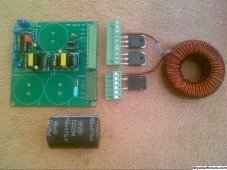
I'm adding the capacitors to the Pcb (eda), (so many choices) from your image, I can't id which C# is ceramic & which C# is maybe polyester, electrolytic etc.
Can you possibly take some more pictures from different angles, hopefully showing the C# on the circuit board?

Or alternatively list the capacitor type to each C# on your circuit board?
Mainly C2 - C10,
( I think I can figure out C1 & C8 (polarized).
Thanks.


anolog mppt 01.jpg
 
C1 is 20uF 16v BIPOLAR electrolytic. (Not a standard polarized electrolytic)
C2 10nF polyester 50v
C3 1uF polyester 50v
C4 10nF polyester 50v
C5 10nF polyester 50v
C6 not used
C7 1uF ceramic 50v
C8 10uF electrolytic 16v
C9 1uF ceramic
C10 2.7nF polyester 250v

C11, C12, and C13 really depend on the voltages and power level, but 470uF might be a good start.
When you have that, some of the resistors and the potentiometers will be different, because your solar and battery voltages will be different to mine.
More on that later......

There are some 250uH 20 amp dimmer chokes advertised on e-bay right now that might be ideal.
https://www.ebay.com.au/itm/275535486496?hash=item402731de20:g:k-oAAOSwiTdjbc~m&amdata=enc:AQAIAAAA4K5rmi2m6eZ9pJakwftSlCINzucyH6ghO5pc0C3mwUopPq0fsOitVfp2rwHeu4JR6vbugC/DY7MNGTrFRPKAffltOY6EfBW9+7429OC8WxOfB99Kbhc5fVb0c5SYQYvDG8VYUHfpCL06ctPK8Sdl96s7dsoDdNhtVNjtRTW1X6zwPWjk3VOjUINKBsXYjZpPPhK/dX1EeQlvVJqbWfoort/nzm9GGH/tMB0P/6P7hrgBLPbYPaBgGj5YoWJaMAeYAwM2K8LCWIxTouFhGEBEj1twDr3HnuRp9eS/rxoJCNCc|tkp:Bk9SR7TjzNiJYw
 
Last edited:
C1 is 20uF 16v BIPOLAR electrolytic. (Not a standard polarized electrolytic)
Awesome thanks.
Close to finishing the 1st stage of 3 with easyeda, though pcbway is having a 50% Xmas discount on boards & added components. I think once you get familiar with the program it should only be a 10 minute job (stage 1), beginner ~ >10 hours.
 
Suggest you get all the capacitors first, before laying out the board.
Hole spacing's and sizes can vary quite a bit, depending on what actual capacitors you finally end up with.

Selecting the resistors and potentiometers to suit the solar and battery voltages.
Taking the solar voltage first.

The internal voltage reference within the TL494 will usually be just a fraction over 5v, typically 5.05v.
If we make R5 5.1K, the PWM duty cycle will self adjust until the voltage across R5 is the exact same 5.05v.

There will then be almost exactly 1mA flowing through R5, and also through RV1 and R12.
Or looking at it another way one volt per K ohm voltage drop through each.
If we select for RV1 a potentiometer that can be adjusted between 0 and 50K, the voltage drop across RV1 can be adjusted from 0 to 50 volts.

In my own setup, I am running four nominally 24v panels in series, and from memory the max power voltage is supposed to be about 125v.

I wanted a suitably large range of adjustment to experiment with.
With just R5 and RV1 we would have 5v to 55v adjustment range (5K to 55k).
If we include an extra 100K resistor R12 to that, it adds an extra fixed 100 volts on top of RV1 and R5.

So minimum solar voltage adjustment will be 5.05v + 0v (pot at minimum) + 100v = 105v
Maximum solar voltage will be 5.05v + 50v (pot at maximum) + 100v = 155v
That gives heaps of tweaking range either side of the expected maximum power solar voltage of 125v

The battery voltage adjustment works exactly the same.
In my case I have thirty Lithium cells charged to 3.45v.
Thirty x 3.45 = 103.5v

R8 will always be 5K1 = 5 volts.
RV2 will be 10K giving ten volts of adjustment range.
R4 will be 91K adding 91 volts on top of RV2 and R8.

Minimum battery adjustment range 5v + 0v (pot at minimum) + 91v = 96 volts
Max battery adjustment range 5v + 10v (pot at maximum) + 91v = 106v

Suppose you have a 12v battery and you want to adjust charging voltage between about 13v to 15v for example.
That is a two volt range, so use a 2K potentiometer. Add to that 8.1K (8.1 volts)
Minimum 5v + 0v + 8.1v = 13.1v
Maximum 5v + 2v + 8.1v = 15.1v

R1 and R9 the two ten ohm resistors can be completely eliminated and replaced with a solid PCB track.
Sometimes resistors are needed in those two positions when optimally tuning a feedback loop.
In this case there was no need for super fast optimally damped feedback.
Its all a lot simpler and more stable by slowing down the feedback.
It still responds extremely fast, compared to a perturb and observe controller.

If you do run into any feedback instability, which is unlikely, just make either (or both) C1 and C3 larger.
A bit of experimentation should fix it.
 
Last edited:
Back
Top