diy solar

diy solar

Single vs. Multiple Class-T Fuses

AHTrimble

Solar Enthusiast
Joined
Nov 26, 2022
Messages
199
Location
SW USA
I recently sent a private message to Will (Will Prowse) regarding Class-T fuses. Hey, why not go to the master, eh?
He asked me to post this question out in the open for all to see...and enjoy.
So here goes...

In all your dual-inverter system builds I notice a Class-T fuse for each inverter vs a single Class-T fuse right after the battery bank.
Can you explain the reasoning please?

The question is not why to use a Class-T fuse, that is obvious, but why one Class-T for each inverter.
My understanding is the surge from the battery bank to the inverter(s) needs to be interrupted...hence the need for a Class-T.
So wouldn't a single Class-T handle that since it is between the battery bank and the inverter(s)?
The theory/concept/principle behind this is interesting to me. And, I want to make sure I am doing my up-grade correctly.

[ @Will Prowse ]
 
Is it because it’s isolating the two inverters from each other also? As in the malfunction is coming from the inverter?

Also, wasn’t he using EG4 inverters that don’t have a battery CB?
 
Last edited:
I recently sent a private message to Will (Will Prowse) regarding Class-T fuses. Hey, why not go to the master, eh?
He asked me to post this question out in the open for all to see...and enjoy.
So here goes...

In all your dual-inverter system builds I notice a Class-T fuse for each inverter vs a single Class-T fuse right after the battery bank.
Can you explain the reasoning please?

The question is not why to use a Class-T fuse, that is obvious, but why one Class-T for each inverter.
My understanding is the surge from the battery bank to the inverter(s) needs to be interrupted...hence the need for a Class-T.
So wouldn't a single Class-T handle that since it is between the battery bank and the inverter(s)?
The theory/concept/principle behind this is interesting to me. And, I want to make sure I am doing my up-grade correctly.

[ @Will Prowse ]
Mine has a single Class-T fuse with dual LV6548 inverters. That's how I've seen most similar setups on here. Now, I'm looking at adding a second battery bank and if I do so there will be a second fuse for it, but that has nothing to do with how many inverters I have.
 
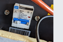
Another unanswered question I posted here before, a lot of those rack batteries use AC circuit breakers. What’s up with that?
AC breakers on DC circuits...uh oh! Not a good situation...but job security for firefighters.
 
Mine has a single Class-T fuse with dual LV6548 inverters. That's how I've seen most similar setups on here. Now, I'm looking at adding a second battery bank and if I do so there will be a second fuse for it, but that has nothing to do with how many inverters I have.
Bingo! I thought the whole idea was to protect everything else from a battery bank.
If you have two battery banks then you protect each bank from each other...and everything else from both banks.
I am looking at protecting each battery with a Bluesea MRBF fuse but I am not ready to take that step yet.
 
Another unanswered question I posted here before, a lot of those rack batteries use AC circuit breakers. What’s up with that?
You forced me to walk out and check mine! :ROFLMAO:

The SS Lifepower4 batteries have a CHNT CB-125A breaker, or at least mine do. Looking at the specs I can find the working voltage is specified at AC230V/DC60-110V and 125a. I can't speak to any other brands but I have to think it would be a concern if it's true, yep.
Yes, I think they switched out the breaker on the newer models. But other brands are still using AC breakers.


EG4 LifePO4
1678288334696.png
 
Last edited:
Yes, I think they switched out the breaker on the newer models. But other brands are still using AC breakers.


EG4 LifePO4
View attachment 138649
This must be a very old photo. For over a year or two, it's all been DC rated.
 
I recently sent a private message to Will (Will Prowse) regarding Class-T fuses. Hey, why not go to the master, eh?
He asked me to post this question out in the open for all to see...and enjoy.
So here goes...

In all your dual-inverter system builds I notice a Class-T fuse for each inverter vs a single Class-T fuse right after the battery bank.
Can you explain the reasoning please?

The question is not why to use a Class-T fuse, that is obvious, but why one Class-T for each inverter.
My understanding is the surge from the battery bank to the inverter(s) needs to be interrupted...hence the need for a Class-T.
So wouldn't a single Class-T handle that since it is between the battery bank and the inverter(s)?
The theory/concept/principle behind this is interesting to me. And, I want to make sure I am doing my up-grade correctly.

[ @Will Prowse ]
The manual recommends an over current protection device for each unit. So I add one. Each device has its own internal fuse. So the individual t-class fuse is only protecting that short bit of wire between the unit and the fuse. But a huge issue that I have is that people will connect a battery without a fuse, not read the manual, and have another 48 Volt battery that does not have over current protection, and connect it directly to LV 6548. So in all the pictures, and in all the diagrams l, I do what they recommend in the manual. I want it clearly seen that we have some form of over current protection device. Especially for videos that usually get over a million views.

Next is peace of mind. I don't know what the AIC rating of the internal fuse is. And if you create a battery bank that is extremely large, I could imagine that little internal fuse not working to extinguish the arc.

Next, we use t class fuses because they have an amazing disconnect rating. The AIC is usually 20,000 Amps.

And no, the server rack batteries are not using AC rated circuit breakers any longer. That was an issue that we talked about multiple times and it has been resolved. I challenge anyone to buy a server rack from the recommended suppliers today and get a AC rated circuit breaker. Post it here.
 
In all your dual-inverter system builds I notice a Class-T fuse for each inverter vs a single Class-T fuse right after the battery bank.
Can you explain the reasoning please?

If you add a battery in parallel, it too should have a class T fuse, so that means each pack should have a class T fuse. Now, the limit per pack can be, what, 200A, so good, put a 200A class T fuse per pack. Let's assume we have four of these in parallel now, and a 5kW inverter without a fuse, and something goes wrong with the MOSFETs in the inverter.

Under normal circumstances, you would not draw more than 100 something amp on that inverter at full load. Now something goes wrong and you start pulling 200, 300, 400, even 800A from the parallel batteries and no fuse stops this because we're not exceeding the 200A per pack. If the inverter was protected with, say, a 125A fast acting fuse, you could prevent damage in your wiring to the inverter, and burning up the inverter itself.
 
Great info!!!!

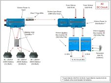
So according to Will's info...generally I think I have it right. Would love feedback on what my plan is!!

My inverters each have a dedicated 200a MEGA fuse in the PowerIn (Distribution).
Each of my charge controllers have a dedicated 100a MEGA fuse in the PowerIn.
Each of my charge controllers also have an Outback 80a CB between the PowerIn and the charge controller.
My Victron Lynx Shunt has a 325a CNN fuse on the positive side of the 1000a busbar.

From the batteries, each battery has a 125a Outback CB in a Quadbox.
2/0 cable connects each battery to the Quadbox and on to the PowerIn.
Then immediately after the PowerIn (1000a busbar) I have a 400a Class-T fuse connected via a tinned copper bar.
Then the 4/0 cable connects the busbar & Class-T fuse to the Lynx Shunt.

Would like to hear what you have to say!

DC Circuit-1.jpg
 
I used to see a lot of breakers in the US that only showed the AC rating on the breaker. It doesn't seem to be as common now, but part of the issue was the specific requirements for DC application were more complicated-- wiring configuration, application as OCPD vs switch, series rating with other protective means, etc.

That might be, but this is an IEC breaker (like used in Europe), and here the rule is that it has to be stated on the breaker.
 
Square D QO breakers aren't DC stamped but apparently can be used for DC up to a particular voltage per their datasheet.

I just wish stuff was printed on everything, removes any question.
 
Square D QO breakers aren't DC stamped but apparently can be used for DC up to a particular voltage per their datasheet.

I just wish stuff was printed on everything, removes any question.

Is that all QO breakers or just QO/QOB 48vDC 5kA ?
 
Back
Top