diy solar

diy solar

Solar Assistant (Possibly) Voids Warranty on EG4 Inverters?

wildbillpdx

Solar Enthusiast
Joined
Jun 24, 2023
Messages
402
Location
Oregon
I just received this from EG4/Signature Solar support:

"I'm glad to see the system is running again, although I would personally not advise using Solar-Assistant as it will burn up the communication card of EG4 inverters. It sends an additional 32V back into the port it's connected to. Also it voids the warranty of EG4 inverters since it is an unsupported configuration."

So I have to say, WHAT? How does that work? The Raspberry Pi is only 5 volts. Has anyone else been told this? I'm using the same cable that comes with the inverter, used by a Windows computer to update firmware on the inverter. Does that mean that a firmware update can damage the inverter (6000EX)? Anyone from Signature want to chime in? @BenFromSignatureSolar ?
 
Don't know about the 32V comment. If that comes from anything, more likely from the EG4 inverter.

Things connected to USB can cause damage, due to common-mode voltages etc.
If done with a laptop (AC adapter not carrying AC ground through to computer) that is less of a problem.

I've had switching power supplies drive about -8V transient when powered on. That blew out I2C port of device under test the computer was connected to. Although the computer was on an AC adapter, it had USB cord to a scope that was plugged in. My solution was a decent linear bench supply.

I'm curious what they have to say for themselves.
 
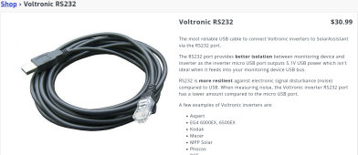
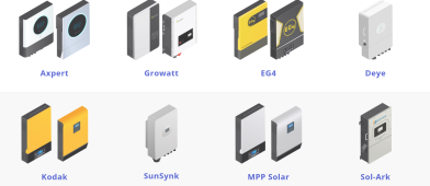
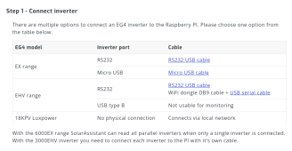
These screen shots are from the Solar Assistant website so I can't see how it would void any warranty if you look at the image of the cableScreenshot 2023-08-29 at 19-21-05 SolarAssistant.png:

Screenshot 2023-08-29 at 19-15-38 Real-time solar monitoring from a Raspberry Pi SolarAssistan...pngScreenshot 2023-08-29 at 19-15-56 EG4 monitoring from a Raspberry Pi SolarAssistant Software.pngScreenshot 2023-08-29 at 19-16-29 Connecting a EG4 inverter.png
 
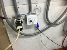
Here are pictures of the Pi and connection to the inverter.
 

Attachments

  • IMG_0838.jpeg
    IMG_0838.jpeg
    221.4 KB · Views: 56
  • IMG_0839.jpeg
    IMG_0839.jpeg
    292.3 KB · Views: 55
Thanks for the pictures and screenshots. Generally those are super helpful when asking for DIY help but this is one case where they don't carry much info.

The product page is kind of confusing in terms of technical specs. Not sure what to expect in seeing a picture of the product vs proper technical specsheet. To be frank that picture carries minimal info for me. All I can conclude is random guessing like whether the USB side plastic mold has enough space for an isolation chip, and based on knowledge I know that USB does carry voltage, and RJ connectors for this use case aren't standardized so you need to look at how Voltronics assigns the pins.

What you want is ground (of any kind - signal, DC-, ...) power, and signal isolation on both sides. Signal isolation might be achieved with optoisolation or transformer isolation. Ground isolation would be achieved by either unshielded cable or cable grounded on only one end, and a cable type that does not carry any power.

Can you contact solar assistant to find out what isolation is provided by that particular item? For $30 I would guess it has optoisolation, since my general feeling is that $10 adapters off Amazon are non isolated and one would hope the extra $20 buys something.

I think the reason EG4 says it may void your warranty is a cover your ass move. Because there are indeed ways to instantly kill the network card by a not terribly difficult to run into configuration of power supplies and non isolated comms cables and ports.

As Hedges mentioned, floating power supplies can help prevent problems. IMO you should start with proper signal isolation. And then add safer power architecture as an extra safety. Since even if you understand what's going on you may miss things like needing to stick to a safe power up sequence or transient power states.

While all non isolated non optical cables can potentially fry things (USB and HDMI being probably the most common examples), when you start doing something as complicated as solar, vs just plugging together computers or home theater, the chances of something breaking from this goes up a lot.
 
Last edited:
First, not using the SA cable, but one from Signature Solar. SS provides a USB to Serial cable and then a serial to RJ45 for connecting to the inverter for firmware upgrades. SA uses that cable to communicate with the inverter. Second, the email I received states that the Raspberry Pi running SA sends 32v back to the inverter and will burn up the inverter's communication card. How can a 5volt device send output of 32v?
 
First, not using the SA cable, but one from Signature Solar. SS provides a USB to Serial cable and then a serial to RJ45 for connecting to the inverter for firmware upgrades. SA uses that cable to communicate with the inverter. Second, the email I received states that the Raspberry Pi running SA sends 32v back to the inverter and will burn up the inverter's communication card. How can a 5volt device send output of 32v?

I didn't have the mental cycles to parse all the entities involved here unfortunately.

Well one case I know of of 5V device sending out over 32V is if 5V device is powered from a 48V to 5V non isolated buck converter. That could potentially be 43V to 48V above ground reference. Well known issue in Power over Ethernet.

Common way for someone to get screwed with that is powering a cable modem off PoE with non isolated supply. The DC- being at, say, 36V for a typical 12Vdc supply, but the signal ground from the coax coming from the cable company being at 0V, is not a happy situation for the circuit board, to say the least.

In solar case you also have 24v or 48v power rail but electronics that need 5v. How would EG4 know the converter type you are using? Vs telling you the scariest worst case but plausible bad situation
 
In solar case you also have 24v or 48v power rail but electronics that need 5v. How would EG4 know the converter type you are using? Vs telling you the scariest worst case but plausible bad situation
That's fine, I can understand that. I'm using a standard "wall wart" power supply for the Pi plugged into an outlet.
 
Floating AC to DC converter for your RaspPi will not have 32v popping out. But as I said, double up the safety measures to hedge against me not knowing what I'm talking about / you not understanding / either of us not translating properly from theory to practice.
 
The wall wart is going to be floating since that's required for safety certification. Otherwise you may have 115 to 120V from ground with some fault combinations which is not a good day for someone touching the USB shield plugged into the wall wart.

Inside the wall wart the DC side is isolated from the AC side etc via a small power transformer. Which means the DC output will end up being referenced against the other side of that RS232 chain, if that chain is not isolated.
 
Looking at EG4 equipment funny voids the warranties. They sure are quick with warranty voids, return denials, processing fees, etc..
 
I think BigClive or some other similar channel has videos of some "suicide" charger wall warts from Russia or something that do indeed develop that line voltage on the "5V low voltage" output. ?
 
So, there's another post here where Signature Solar made up something similar about Solar Assistant putting 12v into that comm port.
Feels like they have two issues: tech knowledge and trying to get out of all warranty.
 
USB adapter built into wall outlet - check whether USB connector shell has continuity to AC ground wire.
If so, it can be a path to carry current that could cause damage.

1693367950213.png
 
Latest response from SS tech support:

"A computer does not send an extra 32V to the communications port so it would be supported. The 32V extra volts from solar-assistant burn up the Communication Card. We've tested it extensively and thus far It's burned up 100% of the EG4 inverters we've connected it to so in turn it is an unsupported configuration at this time."
That's funny. I had SA connected to 4 different 6500s with various cables and never burnt up my communication boards.
 
This all sounds a bit crazy to me. I would think one of the higher ranked people at SS would come here and clarify.
 
I suppose it could be the Orange Pi device sold by SA vs Raspberry Pi...either way I have my doubts. If it was destroying EG4 inverters I'd think there would be all sorts of complaints. SA even touts EG4 on their web site.

Updated information from Solar Assistant support:

I will reach out to our contacts at SignatureSolar to gather more information. Since they are the supplier of your inverter, it's best to follow their guidelines.

We haven't heard of an EG4 inverter experiencing "burn up" due to a SolarAssistant connection. The PI runs on 5V and has a voltage regulator. If you power a PI with 32V as an example, it will flash an intermittent red light while the voltage on the USB ports stay 0V. If you connect it back to 5V there is a chance it still just flashes the red light and will never work again if the voltage regulator was damaged. Otherwise it boots up as normal.

Note that even if the PI didn't have this protection and it's USB port somehow experiences an over voltage, then it still has to go through the RS232 cable/chip before reaching the inverter. For interest sake I'll test what happens when a RS232 cable/chip experiences an over voltage of say 32V, whether it passes through to the other side or not.
 
Back
Top