diy solar

diy solar

Solar Charge Controller with 200 watt panel and more...

WorldwideDave

New Member
Joined
Mar 5, 2024
Messages
67
Location
90266
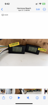
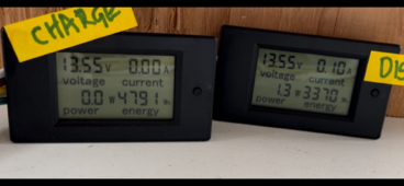
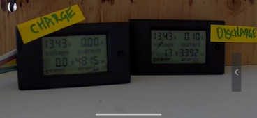
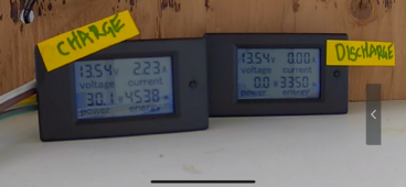
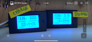
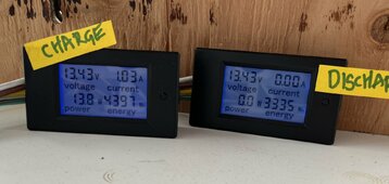
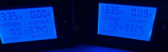
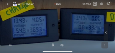
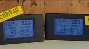
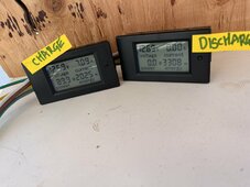
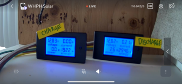
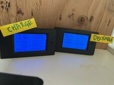
Hello I am trying to diagnose a small DIY system. I think the panels are charging, just not certain. No expensive battery monitor. The SCC has a battery voltage on it, and I have a shunt with 2 meters connected to it - charge and discharge being monitored. The 'discharge' meter shows just fine - when I draw 12v loads (no inverter yet) from the LFP battery, it displays current, volts, watts just fine. The 'charge' meter used to change numbers when the solar was charging the system...but it has not for 2 weeks now. Here's my gear:

12v LiFePO4 battery (12v 200Ah CHINS).

Solar Panel 200 watts. (SP200 max power voltage 19.8V, max power current 10.1A, open circuit voltage 23.7V, short circuit current 10.6A)

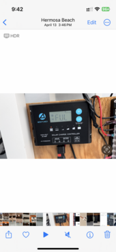
20A solar charge controller (Acopower rated solar panel amps 10/15/20, normal solar input voltage 15-22, max solar voltage at no output load 25 volts).

Shunt meter (will recommended ones - have 2)

It seems strange that the meter would stop working. The wires are firmly installed. It looks to me like the solar panel never puts out more than 24 volts, and the max voltage by the solar controller is 25 watts, and the panel doesn't send out too many amps (10.1) and the solar charge controller seems to support 10/15/20, so seems within range?

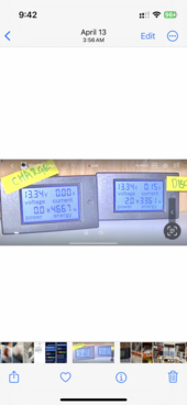
I have really loaded the battery up to where it has lowered the voltage down to say 12.8 volts. But the voltage does seem to go back up to 13.2 or so daily.
I am thinking that I have a bad meter on the 'charge' side.

I suppose I could remove the meter from the charge and discharge sides, and swap to see if it is one of the two meters and not the wiring or SCC.

Is there a better way to test all this without buying a victron or expensive shunt? I do have a clamp amp meter. Solar panel connected with anderson connectors, so putting clamp amp meter around that may be a challenge as they are connected to one another. In other words clamp would go over postive and negative from the panel.

The panel does have a light on it to show voltage is hitting panel, so the fact that it lights up shows me the panel is working at least in some capacity.

Suppose it is possible that i fried the panel in direct sunlight on an extra hot day, but working voltage of the panel goes up to 150.

Related to this is that I think either the BMS or the solar charge controller stops the battery voltage from getting too high. Like the solar charge controller refuses to go over 13.4 volts.

I bought a 15 amp AC to DC battery charger for LFP batteries yesterday and connected it. It isn't super high quality, but when connected it said battery was 13.2 volts and within a short amount of time, it was trying to send it up to 14.4 volts. It is configured for LFP/LI batteries on the display. Why I think there is an issue maybe with the solar charge controller is because the battery should go up to 14.4 volts when charging I would think. See chart for battery below. I never have charged it close to the 40amps it recommends; usually my panel is at 5-6 amps. I am not discharging the battery anywhere near 200 AMPS.

So my guess is that the solar charge controller may have a problem charging this battery (gets to 13.4 and says float, even though in LiFePO4 mode), and the meter I have showing charging that stopped working is bad. Maybe. Open to suggestions/thoughts.

1713824811914.png
 
Should have added this:
1713825470571.png
so I guess for charging, if I saw anything like 13.4 from an inaccurate SCC, then I presume it could be actually 13.6+ volts and be at 100% just fine. So I guess if my new charger is reading 14.4 volts, it is overcharging the battery. But I imagine the BMS in the battery would prevent this.
 
14.4vdc is needed to balance the cells in the LiFePO4 battery, the controller only supplies this level occasionally for a set time. If the battery is fully charged, the controller will show overall panel voltage but the amps will be only what the battery needs to remain topped off. One of the purposes of the controller is to prevent overcharging the battery. If the battery doesn’t need the power (amps), the controller doesn’t draw it from the panels.
 
If I understand your setup you have a shunt meter after your SCC before the battery and an additional one going from your battery to your loads. The one after your SCC is not displaying a charging current to your battery. If this is your problem (and I note that you have a DC clamp on) Do a reading on one of the wires from your shunt to battery while you have sun and the battery is in need of charge. This will tell you if you are getting any current flow from your SCC.

Shunt meters can fail so it is possible that is all it is.
 
No, there is one physical shunt to touch to the negative cable of the battery. Two wires go to the positive and negative posts to power the meter. However, there is one wire on the battery post side of the shunt and another wire on the opposite side of the shunt where the battery cable connects to the shunt. I know it worked because both the meters were working correctly up to a week ago.
 
Last edited:
14.4vdc is needed to balance the cells in the LiFePO4 battery, the controller only supplies this level occasionally for a set time. If the battery is fully charged, the controller will show overall panel voltage but the amps will be only what the battery needs to remain topped off. One of the purposes of the controller is to prevent overcharging the battery. If the battery doesn’t need the power (amps), the controller doesn’t draw it from the panels.
Thanks for your reply. I think the take away here is that no matter what, after buying a LiFePO4 battery, your first purchase must be an A/C to D/C charger for the battery. You must then leave it connected to the charger for a week or so to get it all balanced. THEN you can connect it to your shunt, your inline fuse, your buss, then attach the solar charge controller to the buss, and eventually your loads (inverter/fuse block) to the buss and your panels to the D/C breaker, and the D/C breaker to your solar charge controller.

I did everything like this except I am adding the A/C to D/C battery charger connection to the battery a month afterwards. I have everything disconnected from the battery and the panels disconnected from the SCC right now while I charge.

I believe the other take away is that a dedicated A/C to D/C battery charger should always be connected, and you should not rely on the solar panels exclusively to charge/maintain your battery (or help it get 'balanced' or proper SOC).

Am I right?

Also, what do people do who are completely off grid in the middle of nowhere with no grid power and they just show up with a brand new LiFePO4 battery, not knowing if it is balanced or topped off, and just connect it up to their system like I did?

I heard someone tell me they just built a new system. I was shocked to learn they didn't use LiFePO4 batteries, although they could afford them. Turns out they didn't want to deal with a BMS or any maintenance...their sealed batteries have none of these issues, but instead have different issues I suppose. Not an expert on any of this.
 
Last edited:
No, there is one physical shunt to touch to the negative cable of the battery. Two wires go to the positive and negative posts to power the meter. However, there is one wire on the battery post side of the shunt and another wire on the opposite side of the shunt where the battery cable connects to the shunt. I know it worked because both the meters were working correctly up to a week ago.
Sorry but this does not clear up things for me. Perhaps a photo of how you set the 2 meters and the 1 shunt up would help.
 
I’m out of town at a tech conference. I’ll look through my pictures later. Just assume for a minute that I did wire it correctly because it was working for a month, and now it is not, and it is either a bad solar charge controller not sending any juice to my battery, the meter itself may have gone bad since they cost about seven dollars online, or the panels themselves aren’t creating electricity. But I will post a picture when I can.
 
That makes it rather difficult to do any troubleshooting. Perhaps it would be best to wait until you are in front of your PV system before anything more is done.
 
Here you go. Sequence is wonky. You should be able to see that it was charging and now it is not. I have security camera pointing at them 24/7. More coming.
 

Attachments

  • IMG_8540.png
    IMG_8540.png
    260 KB · Views: 2
  • IMG_8539.png
    IMG_8539.png
    292.4 KB · Views: 2
  • IMG_8426.png
    IMG_8426.png
    1.4 MB · Views: 2
  • IMG_8424.png
    IMG_8424.png
    978.6 KB · Views: 2
  • IMG_8396.png
    IMG_8396.png
    1.1 MB · Views: 1
  • IMG_8384.png
    IMG_8384.png
    1.3 MB · Views: 1
  • IMG_8375.jpeg
    IMG_8375.jpeg
    253 KB · Views: 1
  • IMG_8349.jpeg
    IMG_8349.jpeg
    49.2 KB · Views: 1
  • IMG_8348.jpeg
    IMG_8348.jpeg
    62.1 KB · Views: 1
  • IMG_8332.png
    IMG_8332.png
    1.3 MB · Views: 1
  • IMG_8315.jpeg
    IMG_8315.jpeg
    390.8 KB · Views: 2
  • IMG_8313.jpeg
    IMG_8313.jpeg
    195 KB · Views: 2
  • IMG_8301.png
    IMG_8301.png
    1.5 MB · Views: 1
  • IMG_8239.jpeg
    IMG_8239.jpeg
    161.4 KB · Views: 1
  • IMG_8541.png
    IMG_8541.png
    251.3 KB · Views: 2
what I did was the following patterns to test:
  • have a load in use during the day while the sun was out and charging.
  • have a load disconnected completely during the day while the sun was out and charging.
  • Have a load in use at night when the sun was NOT out and it was NOT charging.
  • Have a load in use during the day with the solar panels disconnected to discharge the batteries. Did this for several days to get the state of charge lower. Did this until BMS shut off battery.
  • Connected PV to SCC to wake up the battery with no load connected
  • Left no loads on battery for a week to see if SCC would read 'Full (FUL)', which it did.
  • Ran loads during the day and night with PV connected
  • This is when I noticed the SCC showing lower voltage on the battery in the morning, then the SCC would show higher voltage battery by night, but the shunt showed discharge fine but no charge
  • Observed it for a week charging and discharging the battery with PV connected, and all appears fine by SCC, but the shunt meter never started showing that it had any charge
Note: The meters themselves show cumulative data unless you push the button and hold it to clear (CLR) the data. So in the photos above you should see that the discharge number keeps going up and up and the charge goes down and down. But at some point, the charge meter just stops showing watts or any change in total watts. These are taken during the day and night to track progress.

Thanks again to everyone who is reading and trying to help.
 
Those meters incorporate a shunt in them. I have used them and not been too happy with having 3 fail after a short while. In my case they lost the ability to display properly so they could not be read.

As I previously mentioned you can do a clamp on meter check to see if you are getting charge from the SCC.
 
I do have a handheld Fluke and Klien meter to measure amps. You are suggesting that I connect everything back up at night, draw a load from the fully charged battery to run the battery down a bit over night, turn off the loads, then in the morning when the sun is out and the panels turn on, I should put the meter around the battery cables to see if current is flowing from SCC to battery, correct? I can't get a clamp around my anderson cables independently - they are close together. My panels came with anderson, so I have not changed it to MC4 yet. Hope to some day.
 
Correction to my earlier post. The 14.4vdc is the absorption mode, not the equalization which is even higher, 16.2vdc. Final float mode is 13.8vdc. At least on the Victron smaller SCCs.
As long as your charging device passes a voltage higher than the battery, the battery will charge. Solar chargers often require a noticeable differential, like 5 volts more, above the battery voltage to allow the power to be sent to the battery. I was just reviewing Victron manuals for a couple controllers I’d like, and IIRC, the panels need to produce that +5vdc over voltage to start sending power to the battery, but will continue as long as it remains +1vdc above battery voltage. Another reason to have some panels in series in the mix, along with less amperage line loss using smaller cheaper wires. The controller starts working earlier in the day, stays working later in the day, with the higher voltage.
 
Thanks for reply. I don’t totally know how that applies to my situation. Can you dumb it down? You saying that somehow that because the battery voltage did not drop enough in a week that the SCC never asked the PVs for any juice? Or you saying that the voltage of my PV did not exceed that of the battery? I am all but certain the PV did. The SCC rotates through the screen showing values and I’m sure it was higher than the battery. One image above shows 71 watt hours (or amp hours?) generated in a single day.
 
Back
Top