diy solar

diy solar

Solar panel circuit breakers ?

Aceallenk

New Member
Joined
Nov 28, 2019
Messages
21
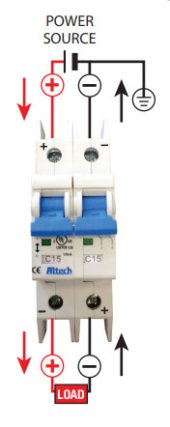
First should the circuit breaker be on the positive lead between the panel and controller, OR should it be on both, positive and negative? Should it be the same Amp as the controller? PLUS what does it do to a solar panel in the sun not connected to controller? Just seems that can't be good for them !!
 
Goes on the positive lead. Make sure it is a DC circuit breaker (IMPORTANT!), and that it is installed in the correct polarity.
If you are parallelling several panels (or strings of panels), they should all go should go to a combiner box, and be individually protected with circuit breakers.
It doesn't hurt the panel to have nothing connected, just as it doesn't hurt an outlet to have nothing connected...no current flows in either case.
 
NEC states you size the breaker between the solar panel (or string of panels) and charge controller by solar panel short circuit current (Isc) x 1.56. So a panel with 7A Isc x 1.56 = 10.92A, round up to next available, probably 12A. Make sure the wire is big enough to handle 12A, not 7A. For the output of the charge controller, it is the rating of the device x 1.25. So for a 20A charge controller, it is 25A, probably round up to 30A.

Just to make it more interesting, you are not required to have over current protection for 1 string to the controller, but you are required to have a DC disconnect. You know what makes a great DC disconnect? A DC breaker.
 
Thanks SolarQueen, Been a slight change of equipment, so am I correct here with my thinking ! My solar panels exact ''short circuit current''is 6.24A per panel, times 3 panels hooked in parallel 6.24 x3=18.72 x1.25=23.4 so a 25A circuit breaker between the solar panels and controller ? and I decided on a larger controller to the 40A MPPT Renogy Rover, 40 x 1.25 =50A so a 50A fuse/breaker between the battery and controller now? I'm using 8AWG pure copper wire for everything.
 
My solar panels exact ''short circuit current''is 6.24A per panel, times 3 panels hooked in parallel 6.24 x3=18.72 x1.25=23.4 so a 25A circuit breaker between the solar panels and controller ?

Based on what SolarQueen posted earlier, NEC states a factor of 1.56, not 1.25 for the PV breaker. This works out to needing a 30A breaker, not 25A.
 
Goes on the positive lead. Make sure it is a DC circuit breaker (IMPORTANT!), and that it is installed in the correct polarity.
If you are parallelling several panels (or strings of panels), they should all go should go to a combiner box, and be individually protected with circuit breakers.
It doesn't hurt the panel to have nothing connected, just as it doesn't hurt an outlet to have nothing connected...no current flows in either case.
I know this is old, but i do want to react for futur reference, a breaker should not be polarised between inverted and battery ... cause current go both ways.
OR a 2 poles polarised breaker wired this way (see pic), cause one of 2 breakers will trip whatever direction the current is going.

Rem : Polarised breaker use electromagnetic field to clear the arc, in this 2 poles example, one will break the arc while the second will not, thus protecting the second breaker ... dunno if it make sense or if i'm clear enough.
 

Attachments

  • 2022-01-02_132230.jpg
    2022-01-02_132230.jpg
    19.7 KB · Views: 12
Last edited:
Hi to all,

The BIG question I have is following:

Why use large diameter cables (70mm² or 2/0 AWG, as recommended by manufacturer of my PV system) when a breaker or switch is placed in the line between battery and inverter ?
When I open some switches to look at the interior switching mechanism, I only see very small contacts to conduct the electricity.
If the diameter of the cable should be "large" do conduct the electricity, why not the same for switches (or breakers) ?

And, if the manufacturer/seller of the switches/breakers state "200A" is this really "capable to transfer 200A of electricity continuously", without too much loss in efficiency (or heat loss), or is it just capable to disconnect 200A in a safe way (regardless of the losses in continuous mode) ?

Thanks for any insights.
 
I size for the Ampacity I expect with 20% margin and size breakers and fuse to protect the wire. As far as switches I just follow the UL rating of the devices. That includes whether they are DC or AC. Switching AC is significantly different than DC in terms of arcing. My DC 300 Amp contactors have arc suppression built in.
 
Last edited:
Back
Top