diy solar

diy solar

Sterling Power Product 12V 60A Battery to Battery Charger BB1260

Yuri

New Member
Joined
Sep 26, 2019
Messages
21
After experimenting with cheap workarounds I finally gave up and ordered Sterling 12V 60A Battery to Battery Charger. While I'm waiting for the package I'm trying to prepare for installation and I'm wondering, what is a real amperage this unit used and real max amperage ever seen it provides to a battery bank?
Based on user manual, they recommended fuses about 80-100Amps, depends of manual version, but I have seen people use a regular Ford transit output (that has internal 60A fuse) and seem have no problems with it (for example, for faroutride seems it works). Does anybody have real numbers? It would be nice to get confirmation that it really pushes about 60A into battery bank, but I have doubts.
Also I have a high quality wire, with very good insulation, and I use it almost everywhere in my build, but, it's only 8AWG. I use two or even four wires in parallel for high current loads, but I'm wondering is it really needed for this DC-DC charger? I think voltage drop should not be a problem, just would like to make sure cable will not overheat. Not sure for how long Sterling will pull real 60A current, if any? Until battery fully charged? (I have 200AH LiFePO4)
 
The Sterling BB1260 will pull 60A while in Bulk (figure up to about 75-85% charge) back off a bit in Absorption (pulling 45A down to about 15A as it tapers) and 15A down to <1A in Float. It will deliver approximately 53A to your batteries while in Bulk... depending largely upon the cable/distance connecting it to your batteries. Personally I wouldn't use a 60A fuse on it, as there's a very decent chance the fuse will blow if the unit is charging full-bore and, say, you turn on a load at your batteries... the unit could easily spike above 60A draw as it attempts to compensate for the load. Put an 80A on it, you'll be fine.
Your appropriate cable size depends on the distance from start batt to Sterling and Sterling to house batts... You have to figure round trip distance of course, but in a Transit I figure max round-trip distance from start battery to Sterling, if you mount it all the way in the back, is about 20'? In which case you want to have 4AWG... or double 8 would be fine. Assuming that your house bank is somewhere in the back too, I'd guess the Sterling would only be a max of 10' round-trip from the house bank, in which case you'd be fine at 6AWG... but not 8 unless you're a lot closer than that.
Bottom line, this is a decent bit of current to be sending down a line, and to make the most of an expensive device, double up your 8AWG on all sides and that way it'll be as efficient as it possibly can be.
 
I’m going to put charger right near house battery, so voltage drop will be on input part, that probably should not be an issue.
 
I’m going to put charger right near house battery, so voltage drop will be on input part, that probably should not be an issue.
Well, it looks like for 8awg at 60amps it can be significant voltage drop, so charger can even go to sleep mode. To be on a safe side It looks like indeed I have to use at least a double wire.
 
Well, it looks like for 8awg at 60amps it can be significant voltage drop, so charger can even go to sleep mode. To be on a safe side It looks like indeed I have to use at least a double wire.
A double should definitely cover you. Best to always err on the safe side with these things, especially given that they're not cheap units... you want to squeeze every last available mA out of the thing.
 
I'm thinking about one more thing. My van often sits for months on driveway and van battery become low. Before I have B2B charger I could use battery kill switch to connect car battery directly to my home battery/solar. I didn't start/drive van this way, and used it just to charge a little van battery, so van can be started. With B2B charger I would like to have this emergency charging possibility. The way I'm thinking about is:
- keep Sterling output always connected to house battery;
- add 100-150A dual throw switch, in first (normal) position it will connect Sterling input to car battery output, in second, (emergency charging) position it will disconnect Sterling input, and connect car battery directly to house battery.
But I have a hard time to find appropriate switch able to handle 100-150A current. I see some have 3 positions: 1, 1+2, 2 - but I assume they can not be used, because in 1+2 position it will short Sterling input to Sterling output that probably may fry the charger.
Is there any good 100-150A 1,2, but not 1+2 switches? The only thing I found so far is https://www.amazon.com/YaeTek-Disco...ouble+Throw+Switch+100a&qid=1576276929&sr=8-5
 
The Sterling BB1260 will pull 60A while in Bulk (figure up to about 75-85% charge) back off a bit in Absorption (pulling 45A down to about 15A as it tapers) and 15A down to <1A in Float. It will deliver approximately 53A to your batteries while in Bulk... depending largely upon the cable/distance connecting it to your batteries. Personally I wouldn't use a 60A fuse on it, as there's a very decent chance the fuse will blow if the unit is charging full-bore and, say, you turn on a load at your batteries... the unit could easily spike above 60A draw as it attempts to compensate for the load. Put an 80A on it, you'll be fine.
Your appropriate cable size depends on the distance from start batt to Sterling and Sterling to house batts... You have to figure round trip distance of course, but in a Transit I figure max round-trip distance from start battery to Sterling, if you mount it all the way in the back, is about 20'? In which case you want to have 4AWG... or double 8 would be fine. Assuming that your house bank is somewhere in the back too, I'd guess the Sterling would only be a max of 10' round-trip from the house bank, in which case you'd be fine at 6AWG... but not 8 unless you're a lot closer than that.
Bottom line, this is a decent bit of current to be sending down a line, and to make the most of an expensive device, double up your 8AWG on all sides and that way it'll be as efficient as it possibly can be.

I have the 3Oamp model, so seeing ~23amps delivered to the house battery during bulk is normal? I'm using 6awg wire with short runs, maybe two feet at most from starter battery to charger.
 
I have the 3Oamp model, so seeing ~23amps delivered to the house battery during bulk is normal? I'm using 6awg wire with short runs, maybe two feet at most from starter battery to charger.
That's typical, yes, though further dependent on the length of run from charger to your house bank. The most I've ever seen a BB1230 deliver to a bank was ~26.5A, but that was under absolutely ideal conditions on my test bench with oversized cables and a maximum cable run length of 8" on each side, so under any real-world application conditions, your 23A is right in line with what I'd expect to see.
 
This is Sterlings manual.
Note that those distances are round-trip distances and per European standards... so at 10' round-trip (ie, charger no more than 5' from battery bank) the minimum cable gauge for a 30A charger is 10AWG, with a resulting voltage drop of ~2.60%. At 15' round-trip, however, the voltage drop using 10AWG rises to ~3.90% which is well over what we would, in the US, consider an acceptable and safe drop, so at 15' round trip we would specify minimum 8AWG cable be used... and so on.
 
That's typical, yes, though further dependent on the length of run from charger to your house bank. The most I've ever seen a BB1230 deliver to a bank was ~26.5A, but that was under absolutely ideal conditions on my test bench with oversized cables and a maximum cable run length of 8" on each side, so under any real-world application conditions, your 23A is right in line with what I'd expect to see.

Thanks, the run from the charger to the house battery, a single 100ah Battleborn, is about 12".
 
But I have a hard time to find appropriate switch able to handle 100-150A current.

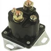
The best way to connect a backup battery to your start battery for emergency use is with a cheap starter solenoid with a remote activation switch (usually a momentary switch).

1578446872347.jpeg
 
but I assume they can not be used, because in 1+2 position it will short Sterling input to Sterling output that probably may fry the charger.

I don't think it should be a problem...if i'm following you right. The charger won't know or care where it gets its power. It should be ok to keep it connected... I'd think.
 
Struggling to visualise this. Where is this 60A coming from, your starter battery? Will the engine be running? If so, consider the rated output of your alternator, especially at idle speeds i.e. minimum cooling. And robbing Peter to pay Paul doesn't sound like a winning design strategy. Charging your 'house' battery from your alternator is definitely a thing but you have to take great care not to overheat your alternator, especially as it will be simultaneously charging your starter battery.

Also, it's generally bad practice to ever directly connect a remote 'backup' battery to a 'starter' battery unless you have absolutely nailed the cable specs - a big engine starter motor can easily draw 800 - 1,000 amps, you don't want this travelling through long cables runs or Li-ion BMS's.

A point of principle: cable size should be spec'd to carry the anticipated maximum load a device requires, fuses are there to protect the cable, so, yes, indirectly fuses protect the device BUT blindly thinking this way is folly. For example, a device requires a continuous 60A, so you spec 85A cable, your fuse should be no more than 85A. Your 60A device will have its own protection and will, therefore, look after itself.

Imho, over-spec'ing cable simply adds unnecessary cost and weight to your project, for no other appreciable benefit. And it's very easy to spec an optimal cable run, no need to guess or 'double-up to be sure', check out this recent post for an example. In short:
(1) Start of with minimum cable size for intended load
(2) Keep voltage drop for anticipated cable run (i.e. there and back) to below 3%
(3) Consider the environmental conditions the cable will be used in

This method works for all cable run challenges*, no matter the current, no matter the length, no matter the intended use.

* DC and low frequency AC only - for higher frequencies you need to also consider skin-effect.

Amazon has hundreds of different types of battery isolator switches, just search 'battery isolator'.

I hope this helps.
Regards,
David.
 
Back
Top