I read though the comments here and I see you have a few issues all coming together to cause confusion. KISS being tossed in here.
First, the charging profile info:
@ 3.65V (100% full) x 8 Cells for '24V pack' = 29.2 Volts.
Low Volt disconnect should be no lower than 22.0V (2.75V per cell)
@ .2C Rate charging (200AH X 0.2) = 40A @ .5C rate = 100A
(generic, applicable to SCC & Inverter/Charger settings)
Set your BULK @ 28.8 (3.6v per cell)
Absorb, float, not needed. if unable to disable, set to 26-28V.
Equalize OFF or 28.0V for as short a time possible.
Low Cutoff 22.0V Hi Cutoff 29.2V
NO TEMPERATURE Compensation !
* Absorb Cutoff is needed: @ 0.01C (200AH X 0.01C = 2A)
Next deration !
Ensure that the SCC, Inverter and everything are on. Have no load demand, so no demand on the inverter & no DC stuff pulling. IF you have a 24V->12V buck converter, do have that on.
Take your DVOM (Digital Volt Ohm Meter) and take a reading on the battery pack terminals, and note it.
Next take the same reading on the SCC (batt side) and note the voltage.
Next, again take a reading on the BATT terminals of your inverter and note it.
These will vary because of the wire used, this is called deration. You have to correct for this. The "true" voltage at the battery terminals is what you need to focus on. If the SCC says it sees 25.5V but at the batt terminals it is 26V then you are losing .5V to the wire, so the values of your setting in the SCC have to compensate for that, because with LFP a 1/2 Volt can man a LOT. This does not apply the same way as it does with Lead Acid Batteries.
Now if you look at your inverter input post voltage, it may be even lower, say 25.3V while the batt is actually 26V. So if you set the LVD cutoff in the inverter to 22V but do not correct, it will cut off at what IT thinks is 22V but in reality it will be 22.7V. IF this is also a charger and you use it to charge and set the Charge Full cutoff @ 29.2 (100% @ 3.65 cell) it will cut off at what IT thinks is 29.2 BUT it will in reality be 29.9 and you've damaged the batteries IF the BMS did not cut it off. We should never rely on the BMS to do that, that is a fail safe mechanism (backup safety). Therefore you have to adjust the voltage settings on your equipment relative to what is actually being read at the battery bank.
** IF you have one battery this is simple, just the voltage off the one battery pack. IF you have more than one pack in parallel, then you take the voltage at the main bus line where all the packs come together. Although it is wise to check the voltage between the packs and the main bus block to be sur that everything is within the same spec voltage.
Excellent Doc from Victron on wiring up your battery bank. See pages 9-12 especially for learning how to setup a properly balanced parallel bank.
The SCC - Changing Voltage: I have never heard of that happening at random. An SCC when powered up, reads the battery and immediately adjusts to that voltage. Most will do 12,24,48 automatically, Victron included. When an SCC goes dead OFF (no power @ battery or Solar) when it get's repowered, it will auto-sense the battery bank voltage and set itself to that. They should maintain the charging profile configuration in non-volatile ram. There is obviously something else going on here, defective or incorrect wiring ? The battery would not do this, it can't go that low to seem like a 12V battery 8 cells @ 2.0V = 16V the BMS would have turned it off by 2.4V per cell (pending on it's programming). To diagnose this, photo's and a logical diagram of your setup would be helpful. It is possible you got a dud SCC, it happens, even with Victron.
Hope that helps...
Steve
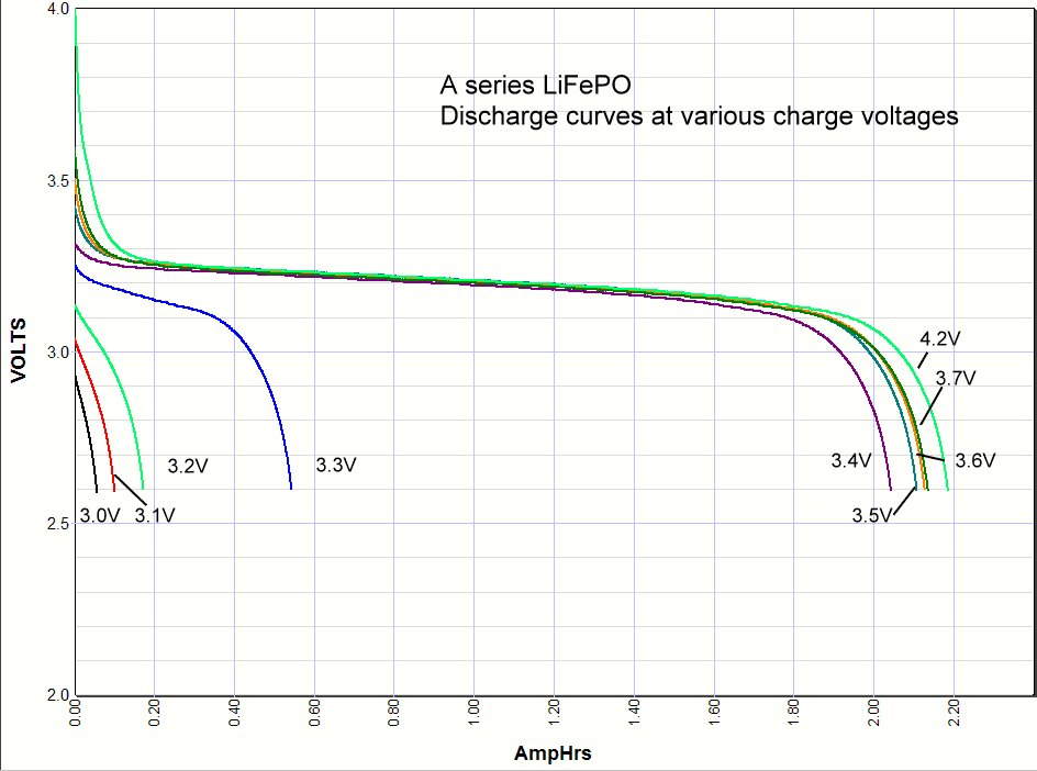
PS: This is a good read, written by Rob Beckers, an EEng and the owner of SolaCity and someone I also consider a friend, he knows his stuff !
By: Rob Beckers You have just sold your first-born into slavery, remortgaged the house, and bought yourself a lithium-ion battery! Now you want to know how to take care of your precious new purchase: How to best charge lithium-iron batteries, how to discharge them, and how to get the maximum...

www.solacity.com