diy solar

diy solar

Using JK-BMS. Do I need a smart shunt?

It’s truly been rock solid for just a few dollars.
Just curious, how many hours did you spend figuring out how to get it working, configuring, fiddling with small wires and breadboards, testing, etc.?
 
Just curious, how many hours did you spend figuring out how to get it working, configuring, fiddling with small wires and breadboards, testing, etc.?
I think I spent two hours on first build and about 1/2hr once connected to inverter and batteries. I had one wire on the incorrect pin.

Most of the first two hours was getting Visual Code running on my MacBook. Once I got past that was able to quickly flash it.
 
@SeaGal
It's amazing all the information you pack into that little bird brain of yours! ;)
Thank you, I'll check that out!!
Thanks - it's had a long time to absorb all the information... the amazing thing is that the knowledge hasn't fallen out (yet!). ;)
 
I have to find a link but buying the jst pin connector for the shunt is the easiest way to get this to work.
 
Personally, here's my status on this whole solar DIY project:

brain-full.jpg
 
I'm just a simple electrician.
Now that the conversation has moved to programing, I'll see my way out. lol
 
Hey guys, particularly @SeaGal @timselectric @ChrisG @shopman

Resurrecting this old thread, now that I have my system hooked up and working, I understand that my inverter decides when to start and stop charging the battery based on the battery voltage, and that process seems to work accurately. The fact that the JK-BMS doesn't know the exact SoC is basically irrelevant. If I want to know my rough state of charge, I have a LCD monitor hooked up to the JK-BMS giving me cell/battery voltages, and a chart on the wall telling me which voltage roughly corresponds to what percentage the battery is charged.

I've purchased one, it's sitting right here, but why again do I need this Victron Smart Shunt?
Is it just so that I can know my SoC is 22.5% as opposed to roughly 20%?

And since I'm not doing any fancy charging logic, I don't understand how having the Smart Shunt communicating with the inverter has any particular benefit. In the future I may want to dump excess PV production into a hot water heater, maybe the Smart Shunt can help with that?

Please set me straight guys, I know I'm probably forgetting/missing something.
 
Last edited:
and a chart on the wall telling me which voltage roughly corresponds to what percentage the battery is charged.
This takes a lot of guessing.
Because voltage at SOC is different. Based on if the battery is charging, discharging, floating, or resting.
So why again do I need this Victron Smart Shunt?
Counting what goes in and out, is the only way to accurately know what the SOC is.
Is it just so that I can know my SoC is 22.5% as opposed to roughly 20%?
Or maybe 30% vs 70%.
I don't understand how having the Smart Shunt communicating with the inverter has any particular benefit.
It can't communicate with the inverter. (Unless you have an entire Victron system)
In the future I may want to dump excess PV production into a hot water heater, maybe the Smart Shunt can help with that?
Nope
It's just a battery monitoring device.
 
Actually the Victron Shunt can communicate with any inverter that uses Pylontech CAN protocols using the ESP32 and the project thread. Mine has been working for more than 2.5 months with an EG4 6000xp without issue and now there is a new version of the code.

As far as why use a shunt, it very accurate compared to trying to use voltage as a measure of capacity like Tim said above.
 
Actually the Victron Shunt can communicate with any inverter that uses Pylontech CAN protocols using the ESP32 and the project thread. Mine has been working for more than 2.5 months without issue and now there is a new version of the code.

As far as why use a shunt, it very accurate compared to trying to use voltage as a measure of capacity like Tim said above.
Chris just to be clear, so you are using the smart shunt to determine SoC, communicating that SoC to your inverter, and your inverter is starting and stopping the battery charging based on that SoC number?
 
Chris just to be clear, so you are using the smart shunt to determine SoC, communicating that SoC to your inverter, and your inverter is starting and stopping the battery charging based on that SoC number?
Correct. The ESP32 and CAN board sits between the shunt and inverter CAN battery port. I have the 6000xp set to Lithium Battery type 2 (for pylon). The esp32 sends SOC, voltage, capacity, etc received from Victron Shunt to the 6000xp.

I have the 6000XP on SOC control for charge, discharge, cutoff, etc. No voltage controls outside of some protection levels.
 
Interesting
I have no need for closed loop communication.
But I do like finding out things that I didn't know, before.
 
Correct. The ESP32 and CAN board sits between the shunt and inverter CAN battery port
Is there a way to use this to create logic to, for example, tell the inverter to dump excess PV production into a hot water heater?
 
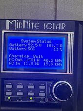
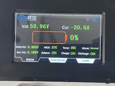
As others have said, the BMS doesn’t seem to do a good job monitoring SOC. Been playing with it today and it’s driving me nuts. I’ve added 2 pictures, one showing my inverters SOC based on a smart shunt (Whizbang Jr), and the SOC from the JKBMS. On the BMS, shows zero SOC, but voltage is fine. Just odd. My inverter(Rosie) uses the Whizbang Jr. to monitor SOC and adjust charging as needed. I’m still figuring it all out, but trusting the smart shunt.
 

Attachments

  • IMG_8992.jpeg
    IMG_8992.jpeg
    146.4 KB · Views: 1
  • IMG_8986.jpeg
    IMG_8986.jpeg
    213 KB · Views: 1
Last edited:
No absolute need for the monitor. If you want it or it seems to have value to you, as it does for many, then go for it.
My Overkill BMS always seems very accurate.
 
Chris just to be clear, so you are using the smart shunt to determine SoC, communicating that SoC to your inverter, and your inverter is starting and stopping the battery charging based on that SoC number?
Yes. Most closed loop systems tell the inverter the SOC of the battery and the inverter will respond accordingly. As @timselectric pointed out the voltage will vary hugely depending on load, so using voltage is largely useless for working out SOC unless you know there is no load present.

The code that @ChrisG is using is the one I linked to in post #15 on page 1 of this thread. I also used parts of that code as the basis for my battery to inverter comms, though in my case I am deriving the SOC from my Overkill BMS, rather than the Victron Smart Shunt. It has been running for over 18 months now, though subject to frequent code tweaks I keep adding ;)

Is there a way to use this to create logic to, for example, tell the inverter to dump excess PV production into a hot water heater?
Of course - it's all just software - anything is possible :). I built an immersion diverter that will dump excess PV to hot water tank. But not just excess, it will also heat hot water from battery and/or solar on a timed basis (in summer, I hasten to add), using data from the ESP32 regarding battery SOC. So it knows whether there is enough stored energy in the batteries to heat water even when the sun isn't shining. More details here if you're interested...

My Overkill BMS always seems very accurate.
Interesting. I find mine drifts over time if you don't fully charge the batteries, usually downwards. So, my BMS reports 100% charge when the batteries have not reached their full charge (as defined by my system with a cell voltage of 3.45V with charge current less than 4A). I have implemented software workarounds to counter that though!
 
Back
Top