diy solar

diy solar

Victron Temperature Sensor Query

aKO

New Member
Joined
Jan 3, 2022
Messages
45
I have posted on the Official Victron Forum and two Victron Facebook pages asking if anyone could identify a Victron Temperature sensor but so far no one has so i thought would try here on the hope someone can say yes or no from experience and knowing something no one else seems to . It might be that both are the ASS000001000 but possible made later or for some other reason are only different in appearance .

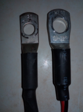
I bought a Multiplus that came with a sensor (ASS000001000 slightly fatter body on the right ) , the sensor is used on several pieces of Victron equipment including my MPPT so i used it for that as it was more important for the MPPT adjust temperature compensation than the Multiplus charger . I have now acquired what i thought was a second ASS000001000 sensor but when i connected it to the Cerbo i found that the Ferrules were only 8mm long and to short so they it kept popping out , when i did manage to get them to stay in i noticed the temperature it gave was 9c higher then the original one despite being connected to the same Battery lug , the two sensors were in direct contact with each other . I then connected it to the Multiplus and the Ferrules were to short for that also . The sensor is a Victron one but im unsure which so im posting a photo of both in the hope someone else might .

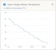
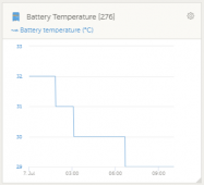
The other anomaly is the data they produce , the one that came with the Multiplus shows increments of 1/10 of a degree ( Right Photo ), , the new sensor Data shown on the left Photo rounds to nearest full Degree , that happens when its connected to the Cerbo and the Multiplus although i don't know if thats down the the equipment and how they normally display the data .
Opera Snapshot_2022-07-07_095617_community.victronenergy.com.png
ScreenHunter 82.pngScreenHunter 83.png
 
Thank you for the information . The sensor i have for the Multiplus but installed on the MPPT is showing a graph similar to your attachments but the new sensor i fitted on the Multiplus is very course in comparison , the data when it was connected to the Cerbo was also as course and now you have informed me that its the equipment that is responsible for the graduations i just need to find what the output of the Multiplus or the Cerbo should look like to confirm i have the wrong sensor , unfortunately i couldn't find any examples online but hopefully someone with either Multiplus or Cerbo wil post a screenshot of the graph theirs produces .
 
Thank you for the information . The sensor i have for the Multiplus but installed on the MPPT is showing a graph similar to your attachments but the new sensor i fitted on the Multiplus is very course in comparison , the data when it was connected to the Cerbo was also as course and now you have informed me that its the equipment that is responsible for the graduations i just need to find what the output of the Multiplus or the Cerbo should look like to confirm i have the wrong sensor , unfortunately i couldn't find any examples online but hopefully someone with either Multiplus or Cerbo wil post a screenshot of the graph theirs produces .

I have done so. Per the linked page, MultiPlus, Quattro, Compatible GX devices (Cerbo GX, Venus GX, etc), VE.Can MPPT, Skylla-S, Sylla-TG and Skylla-iThe use the same sensor.

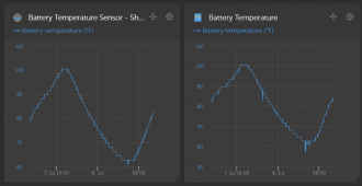
The chart on the right I posted above is the Quattro with its proper temperature sensor.
 
Sorry , i misunderstood , you informed me that its the equipment that provides the display graphs not the sensors and your post showed the displays from your Quatro and BMV , the Quattro using the same sensor my own but i have a Multiplus and Cerbo which is why i would have liked to see a Multiplus Graph also . My older style Blue Solar MPPT CAN 150-80 with the large aluminium case with four buttons and a screen on the front displays the Multiplus sensor as your Quattro and BMV do .
 
Last edited:
The Cerbo GX manual is very clear on which temperature sensor to use, including the part number. It's the same one that comes with the Multiplus. I have my Multiplus temperature sensor connected to the Cerbo GX. I purchased a second temperature sensor (same part number) and it is also connected to the Cerbo GX. The BMV-712 has a temperature sensor also, but it's a different part number. I've never compared the graphs side by side like sunshine_eggo did.
 
Yeah, I didn't even think of that. My Multiplus/Cerbo sensors aren't even on the battery. I'm using them as ambient air sensors.

That works.

Not sure what firmware you're using, but I think at 489 they added low-temp charging protection to the inverter around Oct-2021 if you want another layer... :)
 
That works.

Not sure what firmware you're using, but I think at 489 they added low-temp charging protection to the inverter around Oct-2021 if you want another layer... :)

Multiplus and Cerbo were both updated just a couple months ago. I needed the Cerbo update to get my Ruuvi temp sensors working.
 
Thank you all for your input an patience , Victron equipment and the information it provides is all new to me and Im struggling to get my head around some things . I am clear as to what Sensor i need which is a ASS000001000 , that has never been an issue . My problem is identifying the sensors i have as neither have any part numbers on them other that what's showing the photo .

I have now connected the sensor that came with the Multiplus to the Multiplus and observed the temperature change increments were in fact rounded to a full degree so that settles that query , the same sensor then connected to the Cerbo to use DVCC had to have the offset adjusted down 9 degrees as it was showing far t high but it also only displays full degrees .

Changing the sensors that way i have now confirmed that the data displayed on the graph in VRM is produced by the Equipment the sensor is connected to not the sensor .

If someone could confirm which settings i use on the Remote Consul with the ASS000001000 SENSOR when connected to my batteries , do i select Battery or Automatic .

Is there any relevance to it showing Sensor Voltage of 3.15 Volts or scale which shows 1.0 or product ID A162 .

Is it a Digital or Analogue input .
Below where it says SHARED TEMPERATURE SENSE IT SAYS temperature sensor , do i select BATTERY TEMPERATURE SENSOR 1 or AUTOMATIC

As i cant find anyone that can identify the sensors I was hoping to see a graph produced by a Multiplus or Cerbo to confirm the latest sensor i bought and connected to it might not be a ASS000001000 as its possible it could also be a Type C , ASS000020000 which looks very similar from the Victron data sheets , The one for the BMV has blue shrink wrap ASS000100000 so i discounted it being that one .
 
Last edited:
Back
Top