diy solar

diy solar

What's best device for charge limit control? BMS or Device?

If the BMS is set to cut off at the charger's CV (absorb voltage), no matter where that might be, no CV charging will happen. The battery will only be charged in current limited / CC mode. For the BMS to step in unless a custom configuration is done in the BMS that means targgeting absorb/CV stage over 14.6V (3.65V/cell).

Wapst is suggesting custom setting the BMS down at 14.1V, below the CV / absorb stage of either his chargers so the battery will never see CV mode charging. Makes sense to me.
 
If the BMS is set to cut off at the charger's CV (absorb voltage), no matter where that might be, no CV charging will happen.
If the above means essentially the same as below then I disagree.

{If the BMS is set to cut off at the charger's CV (absorb voltage), no CV charging will happen.}

Absorb phase is not when the charger voltage and battery voltage are equal.
Absorb phase is when the cell can't draw the configured current, because the voltage differential is not high enough.
In order for any flow to happen there has to be a voltage differential.
 
Last edited:
If the above means essentially the same as below then I disagree.

{If the BMS is set to cut off at the charger's CV (absorb voltage), no CV charging will happen.}

Absorb phase is not when the charger voltage and battery voltage are equal.
Absorb phase is when the cell can't draw the configured current, because the voltage differential is not high enough.
In order for any flow to happen there has to be a voltage differential.
This may be a difference in how we are defining the terms.
The most common used terms for the 3 mode charging is BULK ABSORB and FLOAT

BULK charge in my mind is the constant current mode where the charger will keep the current at a set level as the battery voltage is climbing. This puts the BULK of the energy into the battery. BULK mode ends when the battery voltage hits the desired maximum charge voltage. If you are charging at a very high current, and then terminate the BULK charge to no current at all, the battery voltage is going to fall back a fair amount. How far will depend on all of the resistances in the system, including internal cell resistance. This has been described as a rubber band effect. The greater the charge current, the further the rubber band will stretch.

ABSORB charge is normally the time directly after the bulk charge. During ABSORB, the charger will hold the battery terminal voltage constant at the desired maximum voltage. As the actual internal cell voltage climbs closer to the terminal voltage, the current will naturally fall off as the difference between the internal chemical voltage and the terminals become closer so there is less voltage across the internal resistance. The cell is ABSORBING more power and the voltage is stabilizing with the charger constant voltage.

FLOAT charge is not normally used on most Lithium chemistries. If there is a light constant load or the cells have some internal leakage, then it can be beneficial though. FLOAT charge is similar to the ABSORB in that it holds a constant voltage, but it is at a lower voltage so it will just keep the battery from losing charge over extended time. If the battery is just cycling every day, this is certainly not needed. Float is normally used for backup only power system where you want to keep the battery full for a long time.

What you are describing with
"Absorb phase is when the cell can't draw the configured current, because the voltage differential is not high enough."
is the termination or end of the absorption phase.

On cells with very low internal resistance at a lower charge current, the absorb phase could be very short.

As for the original discussion... Let's assume the battery bank is a 4S 12 volt LFP system. To try to get the battery to just 80% charge. I am using guestimate numbers for voltage to SoC, feel free to look up more accurate numbers but I am using a large imbalance to show a point.

Using the BMS to do the cutoff, the BMS is set to terminate charge when any single cell hits just 3.5 volts. That is a total pack voltage of 14 volts. Even if you have a balancer that can pull 200 ma, starting when a cell exceeds 3.2 volts, it won't be doing much at all when the system is charging at say 50 amps. That is just reducing the current to the high cell by 0.4%. If you have one cell that is just 1% down in capacity, it will still be climbing faster than the other 3. That cell will hit 3.2 volts and all charge current will stop. We don't know how far out of balance the pack is, but it won't be getting better. If they were 0.2 volts out of balance, this would be huge. The top cell, which is likely a lower capacity, which is why it charged up faster, has reached the 80% of it's charge capacity, but the other 3 are at only 3.3 volts, which might only be 60% of their capacity. In this setup, you only ever get to use the 80% of the weakest, lowest capacity cell.

Now if the charge controller was set to go from BULK to ABSORB at 14 volts, the current will just start to drop when 14 volts total is reached. If the pack is the same 0.2 volts off balance from the highest to lowest cell, which is very bad, the 3 low cells are all at 3.45 volts when the top cell hits 3.65 volts to reach the 14 volts total. Yes, this is a huge imbalance, but I'm trying to show a worst case here. So the charge voltage will now hold constant and the current will start dropping. That 3.65 volt cell has the balancer loading it to 200 ma, and the charge current is dropping, but still not off. The voltage on the high cell will naturally fall some from the reduced current, and a little more from the balancer load, but the other 3 cells are still climbing. Depending on how low the tail off current is allowed to go, it could drop below the 200 ma of balance current, but in most cases it won't. At some point, the charge current will be down to where the absorb charge just terminates. The longer the absorb lasts, and the lower the current can go, the better the balancer will be able to "Top balance" all of the cells. Even with a short absorb time, the one lower capacity cell might be at it's 95% charge, and the other 3 get to their 79% charge. With a longer absorb, the bottom 3 will creep up more, and the top one will drag down more and get even closer. But your usable capacity get's closer to the good cells 80% and the low capacity cell has to use more of it's capacity to keep up.

If you have higher current active balancing, or much more closely matched cells, then the difference between the 2 setups will get closer. Having a charge controller actually CONTROLLING the charge will make better use of the batteries. Even if you are not targeting a full charge, having it absorb charge at a lower voltage is still good for maintaining balance in the pack. Assuming the balancer can be configured to run below your chosen absorb voltage.
 
I don't think it needs to be all that complicated.
The Chargery BMS will balance at 1.2 A and it can be set to charge at varying thresholds and even in a static or discharge state if desired to force balancing.
When you reach the knee ... there isn't that much capacity left to be had and pushing in more amps decreases the battery life .... if you need more capacity make a bigger battery.
I think the bulk, absorb, and float is thinking left over from lead batteries where they could benefit from this treatment.
 
This may be a difference in how we are defining the terms.
Maybe
During ABSORB, the charger will hold the battery terminal voltage constant at the desired maximum voltage.
Been a while since I tested that but I'm pretty sure that is not what I have observed.
From memory I have observed that the voltage at the battery terminals is still less that then at the charger terminals.
At the very least, the resistance of the wire should drop the voltage a bit.
As the actual internal cell voltage climbs closer to the terminal voltage, the current will naturally fall off as the difference between the internal chemical voltage and the terminals become closer so there is less voltage across the internal resistance.
I can't speak to the internals
What you are describing with
"Absorb phase is when the cell can't draw the configured current, because the voltage differential is not high enough."
is the termination or end of the absorption phase.
I still maintain its the beginning of the absorb phase
Two things happen at the transition from bulk to absorb.

1. The charger no longer has to control the current flow via the only tool that it has, which is voltage control.
This means the charger is putting out the specified voltage not that the battery is at the same voltage as the charger.

2 . The current starts to trail off as the battery voltage converges with the charge voltage and the battery subsequently draw less current.

Imagine that you are charging a single cell without a bms.
If you charge at 14.600 volts the cell voltage will never get to 14.600 volts.
The charge source and the cell approach unity but never actually achieve it.
Which is fine because the cell is considered fully charged when the current drops to ~14 amps.
 
Last edited:
Yes, there will be some voltage difference due to the resistance in the circuit, but as the current falls off in the constant voltage phase, the difference due to the resistance is going to fade away. If you want to go to a few millivolts, sure it may never truly match, but it will get very close when the current gets low. How low the current will go before it just turns off will depend on the charge controller. My charging is done by a Schneider XW-Pro that is AC coupled to my solar grid tie micro inverters. If I allow it to go deep into absorb, the current will go all the way down to just 1 amp into my 360 AH battery bank.
 
I'm not sure if I already mentioned this.
Its a common refrain here that voltage is a poor indicator of SOC.
However at the upper and lower extremes it's pretty good.
 
opinions here.

 
where does “the knee” start in people’s opinion?

While I am not the most informed on this topic, here are my thoughts:

The best way to determine this for your particular situation is to do a full charge and discharge cycle and record the data, this will give you data specific to your cells. If this is inconvenient and/or not possible/practical, you should review the cell manufacturers datasheet specific to your cells, they usually publish charge and discharge curves (or at least discharge curves) at different C rates and sometimes temperatures.

Where exactly the knee begins is a factor of the specific cell characteristics, C rate, temperature, etc. My understanding is that it is more of a loose conceptual term that refers to the point at which the graph gets steep, and that it would be somewhat fruitless to try to define a particular point/voltage too precisely.

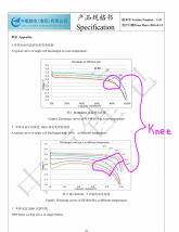
This comes from the CALB SE datasheet, the top graph shows the discharge curve at different C rates but standard temperature and the bottom shows the same curve at different temperatures and a standard C rate (1C in this case). You can see the location of the knee will vary based on both factors (more so temperature).
pg24.png


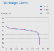
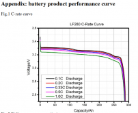
Next here are some 'tidier' discharge charts. With less variation between C rates (temperature is not shown here
The first is the CALB CA series:

Screenshot_2020-10-11 Text operators for PDF - CALB_CA pdf.png


The next is the EVE LF280N

Screenshot_2020-10-11 德赛能源科技有限公 标准文件 - LF280 (3 2V 280Ah) Product Specification(Version E)-201...png

In both cases the knee can be easily recognized and doesn't differ too much based on C rate, In both examples we can probably agree the knee begins somewhere below 3.2V and above 3.0V, it may be a bit tighter than that but its hard to tell from the graph.

Here is another depiction that shows what the knee looks like graphed over multiple charge/discharge cycles as opposed to standalone lab half cycles:

2018-09-19_8-52-12.png

-
 
Last edited:
Chemical cells. Equilibrium voltage. Continuing electro-chemical reactions. By holding the cells artificially above their chemical resting point they will always draw some current. Mass-debate, discuss, argue. :)

Meanwhile back in the practical world we live in, the battery will never experience CV/absorption mode charging for all the reasons stated, most notably being the whole reason this thread exists, it's litterally in the guy's 2nd post.... but what do I know. ?‍♂️
 
...it's litterally in the guy's 2nd post...

For anyone else needing a refresher on the topic at hand, here is the guy's second post:

Guy's second Post said:
in my setup i am trying to operate (set) the operating range of the batteries to be roughly 20% to 80%

my Inverter charger tops out at 14.2v and can't more finely adjust
my solar cc tops out at 14.4v
and based on my testing, i think i want the charging to top out around 14.0 to 14.1 (3.5 to 3.525) to achieve about 80%

so , i was thinking to have the BMS try to keep in the range...

...unless there was a reason not to?

I haven't followed this conversation closely so I may be missing something, but I don't think the plan articulated in the second post is the proper way to accomplish bandwidth limiting, unless it is how the system has been explicitly designed (for instance like with the SBMS0). In the normal (around here) system design, I think BMSes should do the BMSing and charge controllers should do the charge-controlling, unless there is a good reason to do otherwise.
 
Last edited:
I didn't see it mentioned, but 13.8V is high for float voltage. Generally want to float them between 3.3 and 3.4V/cell or 13.2-13.6V.
 
  • Like
Reactions: Dzl
Back
Top