diy solar

diy solar

Why not just switch inverter off instead of using a relay?

Craig

Watts are Watts!
Staff member
Moderator
Joined
Sep 20, 2019
Messages
2,924
Location
Hollister CA and off the grid in Idaho
Will made a great video about using a relay to shut down inverter if battery gets undervoltage.
But there seems to be some discussion as to how long the relay will last and arc's and on an on. The victron battery protect will not work because the capacitators charge too fast when switched on and may destroy the BP.


So with all this in mind why not just repolace the inverters switch with a relay or small MOSFET. this will turn inverter off without worring about how many amps are rushing through the relay. Also it will turn inverter on without rushing amps in to charge capacitors.

It may not be pretty but wouldnt this be a easier solution in the end?
 
if you replace the relay with mosfet , as well you could use the ones in the BMS.
 
I looked at this idea a short time ago, trying to control the power switch on an 'All in one' unit, but the problem i ran into was controlling a 240vAC circuit switch with a 12v DC relay output. Didnt know enough about relays etc to feel confident. :-(
 
Lots of inverters have soft power buttons, press/hold 2 second/release to toggle the state etc. That type of action would be beyond what a typical BMS is doing, but achievable with a little more circuitry including monitoring of say the on LED to know what the state is.
 
Good idea. Some inverters come with a wired remote control. It's easy enough to hack the remote control and tap into it using a small relay triggered by the BMS or an Arduino.
 
The Samlex EVO Inverter/Charger has two contact closure inputs meant to be actuated by a BMS. One stops charging and the other stops inverting. I am in the process of getting this set up, so I can't speak to how well it works, but this is one of the reasons that I picked this unit. It will even display "Charger off by BMS" or "Inverter off by BMS" on it's status screen so you know that the BMS triggered the action.
 
So, I'm wondering about the 'Inrush' and MOSFETs in BMS...?

Now, I use a big contactor to save the batteries, I used them to take lead acid battery strings out of the bank when voltage in them dropped too low.

So with the MOFSETs in the BMS I'm wondering...
Would the command signal to restore power to the disconnect contactor, the under volt protection I use has a timer,
would another timer, 555 maybe, close a fixed resistor/relay say, 5 seconds before the main contactor closes again?
 
I also built mine to shut everything down in the event of a fire.
Smoke detector in series with a thermal switch over my battery bank & control stuff.
*IF* the two agree there is a fire, then the system shuts down and the fire suppression starts.
I don't want my wife burning dinner to hose down a bunch of electrical equipment...
 
So, I'm wondering about the 'Inrush' and MOSFETs in BMS...?

Now, I use a big contactor to save the batteries, I used them to take lead acid battery strings out of the bank when voltage in them dropped too low.

So with the MOFSETs in the BMS I'm wondering...
Would the command signal to restore power to the disconnect contactor, the under volt protection I use has a timer,
would another timer, 555 maybe, close a fixed resistor/relay say, 5 seconds before the main contactor closes again?
These little relay timer boards work in several different modes and are great for such needs. They will start time on positive or negative going going DC signal. The relay is isolated so could switch an inverter off at the power switch, if it has a manual switch that you can go in series with, switch in a charge resister, etc.
 
The Samlex EVO Inverter/Charger has two contact closure inputs meant to be actuated by a BMS. One stops charging and the other stops inverting. I am in the process of getting this set up, so I can't speak to how well it works, but this is one of the reasons that I picked this unit. It will even display "Charger off by BMS" or "Inverter off by BMS" on it's status screen so you know that the BMS triggered the action.
You beat me to it ! LMAO !
If people considered the equipment out there and looked at the specs rather than the $ value, they would realize that sometimes they are wasting more on extras to make up for product shortcomings rather than getting a slightly more expensive device that has the features & functions with it. I know one fellow personally, who spent 3X the amount of money on his inverter & associated "fixes" that he would have if he would have bought a Samlex… what's worse, is after he did it, it all ran for 3 months and then did the magic smoke and toasted it all. So he took $1200 an bought a Samlex replacing about 3 grand wort of new scrap, he thought he could save with... Penny Wise but Dollar Foolish. 3 grand to learn that a 1200 solution could have solved it simply so the total cost of that education was $4200.00 and luckily just that, as the battery packs were not damaged, else it would have been Really Bad !

There IS a gotcha there though too... IF you have more than one LFP Pack and so more than one BMS you need an intermediary to manage all the BMS' & the interaction with the Samlex. This can be done using the Modbus protocol (Samlex has Modbus & CanBus) via a Raspberry Pi running Modbus software programmed to interact with it. Samlex does NOT publish the Modbus protocol stack, it requires a legal NDA, I am not sure about the CanBus protocol. (I have the Modbus protocol info as I am a developing software to work on my systems management package.)
 
That's where i'm at also. I ordered a 120amp BT BMS but i'm still not 100% happy with it. I'm already working on a Arduino project to monitor the Camper Van "status" so I will already have temperature and a really good reading of each battery voltage. Adding a few relay and mosfet I can control charge/discharge, inverter, ceiling fan etc. I can just use a simple 5A active battery balancer and I'm done :D
 
Will made a great video about using a relay to shut down inverter if battery gets undervoltage.
But there seems to be some discussion as to how long the relay will last and arc's and on an on. The victron battery protect will not work because the capacitators charge too fast when switched on and may destroy the BP.


So with all this in mind why not just repolace the inverters switch with a relay or small MOSFET. this will turn inverter off without worring about how many amps are rushing through the relay. Also it will turn inverter on without rushing amps in to charge capacitors.

It may not be pretty but wouldnt this be a easier solution in the end?
Dang good idea.
 
You beat me to it ! LMAO !
If people considered the equipment out there and looked at the specs rather than the $ value, they would realize that sometimes they are wasting more on extras to make up for product shortcomings rather than getting a slightly more expensive device that has the features & functions with it. I know one fellow personally, who spent 3X the amount of money on his inverter & associated "fixes" that he would have if he would have bought a Samlex… what's worse, is after he did it, it all ran for 3 months and then did the magic smoke and toasted it all. So he took $1200 an bought a Samlex replacing about 3 grand wort of new scrap, he thought he could save with... Penny Wise but Dollar Foolish. 3 grand to learn that a 1200 solution could have solved it simply so the total cost of that education was $4200.00 and luckily just that, as the battery packs were not damaged, else it would have been Really Bad !

There IS a gotcha there though too... IF you have more than one LFP Pack and so more than one BMS you need an intermediary to manage all the BMS' & the interaction with the Samlex. This can be done using the Modbus protocol (Samlex has Modbus & CanBus) via a Raspberry Pi running Modbus software programmed to interact with it. Samlex does NOT publish the Modbus protocol stack, it requires a legal NDA, I am not sure about the CanBus protocol. (I have the Modbus protocol info as I am a developing software to work on my systems management package.)
Im all in with the samlex stuff. However if I cant sit around and devise ways to do things where is the fun. Plus all of this is educational in one way or another.
 
Last edited:
So with all this in mind why not just repolace the inverters switch with a relay or small MOSFET.
You'll probably find that the inverter switch will be simply providing a signal to a microprocessor e.g. grounding the line, so you wouldn't strictly speaking have to create a bypass switch, just provide the same signal.

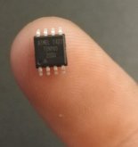
As has been mentioned, most 'higher-end' inverters have programmable everything so such a DIY solution probably wouldn't suit them but for your basic inverter you could probably do this with an AT-Tiny based microcontroller. It has 5 GPIO pins (6 if you bin the reset) so you can use one to provide the switch signal and still have 4 left to monitor voltages or another switch or provide an LED indicator. It only has one PWM pin but this could be used, for example, to drive a buzzer alarm.

OZ1mZIS.jpg
The analogue inputs are, if memory serves, divisible into 1024 levels between 0V and 5V so you could program the battery voltage threshold in 5mV increments. Obviously you'd need a potential divider to drop the battery voltage. You can program in delays, interrupts e.g. on switch press, even fancy stuff like long-press to silence the buzzer.

The microcontroller itself will set you back around £1 (or 20p from China!), complementary components, hook-up wire etc maybe £5 all in.
 
For 12 & 24 volt small systems, 'Start' button trips the resistor for pre-charge on a 5 or 10 second cycle, the second closes the disconnect to close after the 5 or 10 second.


Small relays along side the big contactor, timers control small relays.
One is 'precharge, one is main contactor.
 
Will made a great video about using a relay to shut down inverter if battery gets undervoltage.
But there seems to be some discussion as to how long the relay will last and arc's and on an on. The victron battery protect will not work because the capacitators charge too fast when switched on and may destroy the BP.


So with all this in mind why not just repolace the inverters switch with a relay or small MOSFET. this will turn inverter off without worring about how many amps are rushing through the relay. Also it will turn inverter on without rushing amps in to charge capacitors.

It may not be pretty but wouldnt this be a easier solution in the end?
Thank you I would like to take credit for Will's latest video. Just Kidding but it is nice to see a video validating ones ideas. (y)(y)(y)
 
Will made a great video about using a relay to shut down inverter if battery gets undervoltage.
But there seems to be some discussion as to how long the relay will last and arc's and on an on. The victron battery protect will not work because the capacitators charge too fast when switched on and may destroy the BP.


So with all this in mind why not just repolace the inverters switch with a relay or small MOSFET. this will turn inverter off without worring about how many amps are rushing through the relay. Also it will turn inverter on without rushing amps in to charge capacitors.

It may not be pretty but wouldnt this be a easier solution in the end?
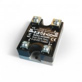
Couldn't you use the Victron battery protect to control the Opto 22 DC60S5 DC Control Solid State Relay ?

61Kv3KHMOeL._SL1000_.jpg
 
Just watched Will's video 'Optocoupler SRR'

Not sure I'm keen on effectively bypassing the BMS' protection circuits just for the convenience of switching a high power load. It obviously works and he does mention in the video about properly configuring low voltage disconnect and absorption voltages etc but some inverters don't even have such features, whereas for others the inverter switch is is processed digitally, a separate SCC would present an overcharge risk etc. Whilst this may work, it certainly isn't a universally applicable solution.

Furthermore, opto-coupling is only needed to galvanically isolate a dangerous voltage circuit e.g. mains voltage from DC in a DC adapter. This system is all low voltage stuff connecting to more low voltage stuff; opto-coupling is just an unnecessary expense. Nothing wrong with it, per se, just unnecessary in this system design.

Edit: Corrected typo.
How would you turn off inverter for cheaper?
Agreed it probably is a very low current switch.
Originally I mentioned using a fet but the SSR is stupid simple.
 
This is a great solution if your only load is the inverter. In a lot of mobile rigs, you have a lot of other DC loads and chargers other than the inverter. On the surface that 'breaks' this idea. However, the fact that the inverter is often 2 or 3 times the load of everything else gives an opportunity to do a hybrid solution:

1) Set up the inverter like Will shows.
2) Run your other DC loads through the BMS.

Example: If your 'other' loads and chargers are less than 100 amps and your inverter is 200 amps, you could use a 120Amp BMS.

I have not tried this but it seems like it would work.

EDIT: This may not work. See my next post.
 
Last edited:
Back
Top