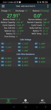
When the BMS is Balancing, you will see the cells indicated in Blue & Red will blink. The Blue blinks when it is discharging to capacitors for transfer of energy, the Red blinks when it is receiving charge from the capacitors. You have set balancing to begin at 3.400 which will start the balancing process when one or more cells cross the 3.400V threshold. The Balancing function will only transfer energy from Hi cells to Lo cells which is what it is doing per your screenshot. Just observe the Blinking indicators and the Balance Current line and you'll see how that is working.
You are also charging Above the LFP Working Voltage Range which is from 3.000V per cell to 3.400 with nominal being at 3.200 (50% SOC) You are better off charging to 3.450Vpc (27.6V) and terminating Bulk/Absorb charge @ 14A which is your Endamps/Tailcurrent. LFP will always settle when no charge current is being applied and that tends to take the cells to around 3.400... it IS the chemistry.
The one cell: The only way to know for sure the state of that cell compared to the others is to test it with a proper cell tester such as a
Yaorea YR1035+ Cell Tester, these are also available on Amazon/EBay - pay attention to where it ships from, you can get one pretty fast if shipped from "local" warehouse. These testers give you the cell voltage & Internal Resistance of that cell. If the cell has a different Internal Resistance as compared to the others in the pack, that will affect the amount of charge it can take and will hold and it
appears you have one weak cell but that is not certain. NOTE that the BMS does NOT read Cell IR, that is just the Cell Sense Lead resistance.
Troubleshooting this:
Rule 1, Assume NOTHING ! Assumptions are great for making asses out of oneself. ;-)
Start at the basics;
- disconnect the BMS (unplug Harness from BMS). Your Cell Wire Resistance shows good but good to verify resistance independently.
- remove the busbars from cells and clean all contact surfaces (bars & cell post/pad) with 99% pure rubbing alcohol. Same with ring terminals used for the BMS sense leads.
-- Now is the time to test Cell IR with Tester, remember to ZERO the tester by touching the tips together till it zeros.
- IF there are any Burrs or Ridges on the busbar holes, file them down, wipe clean again, place "ridge/burr side" Face Up so as to not interfere with cell contact.
- Reinstall busbars and Sense Leads on the (+) Terminal of the cells, torque to 5psi
- Reconnect BMS Sense Harness to BMS
Now charge the battery pack to 27.6V (3.450Vpc) and ensure that it is saturated to where the pack is taking 10A or less current. The cells should be close IF all of them have the same IR +/- 0.02, any greater difference, the further out of synch they will be.
Please Note:
Properly Matched & Batched cells will have identical IR throughout the "Working Voltage Range" of 3.000-3.400 which ensures that the cells will be pretty much at an equal Delta (0.005) within that range whether under load or charge. Once outside of the Working Range the cells will deviate farther apart the more you get from the range (high or low). This is normal for LFP.
Strongly Suggested:
-Do not charge above 3.450, set Bulk/Absorb to charge to 27.6V Your EndAmps/TailCurrent is 14A at which point the charger should transition to Float. (Constant Voltage/Variable Current)
- Do FLOAT charging @ 27.6 or 27.5V(3.437Vpc) (some gear requires a 0.1 lower float rate) and you will see Amps taken continues to decrease as the cells saturate to Full. At some point the BMS will just stop taking charge and drop to storage mode, allowing float to service any demand that exists if it has the power available from the solar array.
Allow the BMS to do at least 2 full cycles before its SOC reading is accurate.
Calibrating the BMS !
- Charge your battery pack to full and allowing it be saturated at float voltage.
- Allow the pack at least 1 hour after charging input has stopped to completely settle.
- Turn OFF Charge, Discharge & Balancing on the BMS.
- Take the Pack Voltage Reading at the CELLS (+) & (-) terminals and NOT at the battery pack posts. The cells where the wires to the BMS (-) & (+) post are taken from.
- Enter that voltage on your Settings Page for Voltage.
!! be Certain you are using a Good DMM/DVOM which is at least 2 decimal place accurate ! Also remember to ZERO the DMM by touching the probes together and waiting for the readout to be zeros. IF you see Voltage bouncing around a bit, Magnetic / electrical fields around you can do that. It's okay, just be aware of it. IF IN DOUBT apply Rule of 3, and take 3 separate measurements waiting each time for the reading to settle.
Once Calibration Voltage is entered, then Reenable Charge, Discharge & Balancing functions.
Hope it helps, Good Luck.
Steve


") .
.