georgia088
New Member
I have been reading and trying to do the best I can to understand lifepo4 cells. However, I’m stumped. I have built another lifepo4 105ah pack with eve105 cells. 48v 16s. Data sheet:
These cells are rated for 1c continuous and 3c for 30 seconds. I have built a pack before with the same cells and really haven’t had issues with the other pack, but it is my dads pack and he only uses it sparingly. I built them for golf carts.
I got the cells put together and did a top balance by placing an adjustable voltage supply set to 57.6 with a current of 5 amps. I set my jkbms with 1 amp of active balancing settings to:
Ovp 3.6
Ovpr 3.55
Uvp 2.65
Uvpr 2.55
The pack charged cut on and off until the CC Went to nearby 0 and all cells were really close in voltage. I will try and post a picture of what they were at.
I used the bus bars that came with the cells which are 1mm thick. I also designed a PCB with large connecting traces on both sides to connect the cells in addition to the bus bars. I did this to help the bus bars share the current load between cell terminals, and I also added 1/8th inch traces from each positive terminal to a screw terminal where I connected my bms battery lead wires. I felt I could keep it a little cleaner and neater this way. I left all of the wires the full length that the manufacturer supplied. I will post a picture of my PCB as well. The cells come prethreaded with m4 screws. I didn’t like the m4 screws with the last pack I built so I decided to get m4 studs and lock nuts. I threaded the stud into the terminals with red locktite and let them sit for several hours. I then added my bus bars and the PCB on top of the bus bars and tightened the nuts down to 3.25Nm with a digital torque wrench. I would have gone tighter as I see the spec sheet calls for higher but I stripped one of the threads in a previous cell going to 3.5Nm
I really thought I was doing good by doing all of this. However, I got it all put together and in a golf cart. The golf cart is lifted with a rear seat and large tires, but it only has a 250 amp controller on it. It has a sepex motor. The cart will trip the the 2.65 cell under voltage alarm quickly after taking it off the charger with only me on it. 175lb. The app shows several cells dropping voltage lower than what I think they should at 100% capacity. The amp draw is relatively low as well.
I took a couple of screen videos of the app as I drove it and you can see the voltage sag. I will post a couple of links to the video as I don’t think the site will allow me to post them.
I’m at a loss. I can’t think of anything else I could do. These are brand new grade a (supposedly but how do you really know) cells. Could I have a bad batch? Am I doing something g wrong? The weather was around 45 degrees F but I wouldn’t think that would effect the cells that negatively. Could you please help guide me as to what I should try? I tried to give as much info as I possibly could! Thanks in advance!
https://youtube.com/shorts/-OveXJc9u...fr38yu10IMwm1d
Thanks!
These cells are rated for 1c continuous and 3c for 30 seconds. I have built a pack before with the same cells and really haven’t had issues with the other pack, but it is my dads pack and he only uses it sparingly. I built them for golf carts.
I got the cells put together and did a top balance by placing an adjustable voltage supply set to 57.6 with a current of 5 amps. I set my jkbms with 1 amp of active balancing settings to:
Ovp 3.6
Ovpr 3.55
Uvp 2.65
Uvpr 2.55
The pack charged cut on and off until the CC Went to nearby 0 and all cells were really close in voltage. I will try and post a picture of what they were at.
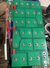
I used the bus bars that came with the cells which are 1mm thick. I also designed a PCB with large connecting traces on both sides to connect the cells in addition to the bus bars. I did this to help the bus bars share the current load between cell terminals, and I also added 1/8th inch traces from each positive terminal to a screw terminal where I connected my bms battery lead wires. I felt I could keep it a little cleaner and neater this way. I left all of the wires the full length that the manufacturer supplied. I will post a picture of my PCB as well. The cells come prethreaded with m4 screws. I didn’t like the m4 screws with the last pack I built so I decided to get m4 studs and lock nuts. I threaded the stud into the terminals with red locktite and let them sit for several hours. I then added my bus bars and the PCB on top of the bus bars and tightened the nuts down to 3.25Nm with a digital torque wrench. I would have gone tighter as I see the spec sheet calls for higher but I stripped one of the threads in a previous cell going to 3.5Nm
I really thought I was doing good by doing all of this. However, I got it all put together and in a golf cart. The golf cart is lifted with a rear seat and large tires, but it only has a 250 amp controller on it. It has a sepex motor. The cart will trip the the 2.65 cell under voltage alarm quickly after taking it off the charger with only me on it. 175lb. The app shows several cells dropping voltage lower than what I think they should at 100% capacity. The amp draw is relatively low as well.
I took a couple of screen videos of the app as I drove it and you can see the voltage sag. I will post a couple of links to the video as I don’t think the site will allow me to post them.
I’m at a loss. I can’t think of anything else I could do. These are brand new grade a (supposedly but how do you really know) cells. Could I have a bad batch? Am I doing something g wrong? The weather was around 45 degrees F but I wouldn’t think that would effect the cells that negatively. Could you please help guide me as to what I should try? I tried to give as much info as I possibly could! Thanks in advance!
https://youtube.com/shorts/-OveXJc9u...fr38yu10IMwm1d
Thanks!