diy solar

diy solar

Seplos CAN BUS RS485 48v 200A 8S-16S BMS

I was using the switch mounted on the PCB. It is marked as RESET on the battery case but ON/OFF in the BMS user guide. Would changing the parameter change the function of this switch?
Correct - the setting is for latching switches vs. momentary buttons.
 
Turns out I can connect directly to the processor and re-flash. However the file supplied for FW update are in an encrypted format which are (presumably) decrypted as they are loaded onto the chip. Annoyingly this means the direct program method won't work.

I had contact from a Seplos engineer who was very helpful but wants the BMS back to re-initialise the unit which will take ages and be a major PITA!
 
Was this got from fogstar.

Yes from Fogstar. I have asked if they can help with:

i) the return and reset of the original
ii) selling me another in the meantime as I assume turnaround time to China is ages

Fogstar don't seem to break any speed limits when it comes to replying, if no response I will phone them tomorrow.
 
I have a bit of SOC drift on my Seplos, reading in here I think it's because I usually only charge to 90%, and a 100% charge will cause it to wait until cell voltages hit limits? I have previously adjusted the SOC to get it to hit them, but I think that is in fact unnecessary?! I think going forward I could just set a schedule to 100% charge every few weeks, or are the BMS settings conservative enough that a 100% charge is not going to affect the life? I don't often need the full capacity of my system.
 
I have a bit of SOC drift on my Seplos, reading in here I think it's because I usually only charge to 90%, and a 100% charge will cause it to wait until cell voltages hit limits? I have previously adjusted the SOC to get it to hit them, but I think that is in fact unnecessary?! I think going forward I could just set a schedule to 100% charge every few weeks, or are the BMS settings conservative enough that a 100% charge is not going to affect the life? I don't often need the full capacity of my system
Seplos BMS v2 resets the soc at 100% charge..
Furthermore I hope you followed instructions to first calibrate the BMS to get a properly set SOC ?
 
And what are these instructions or where would one find them?
They usually come with the BMS. It basically says that in order for the BMS to figure correct SOC with you specific battery, you need to fully charge to 100%, then fully discharge. At least one full cycle for the BMS to learn.
 
They usually come with the BMS. It basically says that in order for the BMS to figure correct SOC with you specific battery, you need to fully charge to 100%, then fully discharge. At least one full cycle for the BMS to learn.

Yes the SOC was calibrated when I built it, although the instructions were no more detailed than your text above :D It didn't explain what I have now deduced, that "100%" is met by either the pack/total voltage being reached OR I think multiple individual cell voltage cutoffs in a certain period.

It did not explain that if you repeatedly charge to (say) 90% and discharge then the SOC will drift and it needs occasional charges to "100%" to maintain accuracy. From what I recall the SOC will sit at 98% and then "pop" to 100% when it decides that the pack is full, using whatever internal rules it has.

I'm using Home Assistant to automate an ME3000SP in passive mode, so I can just schedule a 100% charge once a month or so, no problem now I have it figured. The setup has otherwise run flawlessly for a year, the BMS and ME3000SP are pretty decent bits of kit for the money.
 
Last edited:
Update on my situation. I now have a replacement BMS from Fogstar (who were brilliant), the snag now is it is the wrong 'type' so needs the separate PCB for connectors and LEDs. I will bodge something in the meantime to get back up and running.....
 
Update on my situation. I now have a replacement BMS from Fogstar (who were brilliant), the snag now is it is the wrong 'type' so needs the separate PCB for connectors and LEDs. I will bodge something in the meantime to get back up and running.....
To update again I installed the board minus the connector daughter PCB. The firmware installed is missing all the protocols except Pylontech which worries me somewhat as I was hoping not to risk another FW upgrade. Won't do anything until I have received the daughter PCB.
 
Hi there, just got my kit last week and nearly completed the build but I was sent a V3 board instead of v2.
It's a type B board apparently and I can't find any documentation for connecting the BMS busbars.
Does anyone have a manual or picture of the BMS busbars connected ?
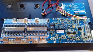
This is the board they sent .....

IMG_20240114_161240_743.jpg
 
Hi there, just got my kit last week and nearly completed the build but I was sent a V3 board instead of v2.
It's a type B board apparently and I can't find any documentation for connecting the BMS busbars.
Does anyone have a manual or picture of the BMS busbars connected ?
This is the board they sent .....

View attachment 188980
It should have come with a 1 sheet instruction manual, but the pictures on it are tiny anyway. There are multiple videos on youtube though:

 
It should have come with a 1 sheet instruction manual, but the pictures on it are tiny anyway. There are multiple videos on youtube though:

That is for the 10E BMS (V2) His does not assemble the same way.

If the case is for a V2, and you got a V3 BMS, I'm pretty sure you are SOL without getting creative and making cables.
 
Definitely sol, looks like they have done the shunt differently in the V3 and hence there is nowhere to connect those two connections now.
 
Definitely sol, looks like they have done the shunt differently in the V3 and hence there is nowhere to connect those two connections now.
Yes, the V2 disconnects the positive side of the battery, and uses the shunt on the negative. The V3 flips that and disconnects the negative and shunts on the negative.
 
Back
Top