G
GridWorks Green Solar
Latest activity Postings About Most reacted threads Most reacted posts
-
-
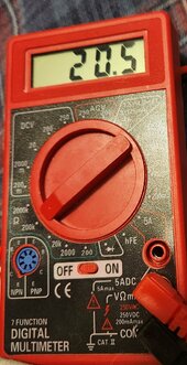
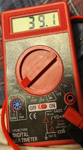
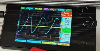
GGridWorks Green Solar replied to the thread New no battery pure sine wave solar power system with smart switchers..With meticulous adjustment and testing of the 50K potentiometers, I have the magic resistive numbers for both channels to provide the...
-
-
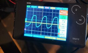
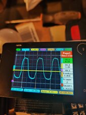
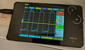
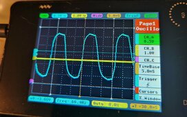
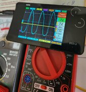
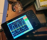
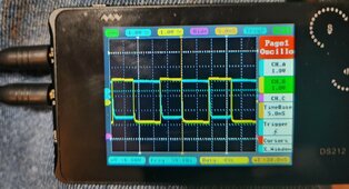
GGridWorks Green Solar replied to the thread New no battery pure sine wave solar power system with smart switchers..This picture is the stereo output of the ISO transformer 60Hz pure sine❤️, Hard to get output from the low end of the inverter just...
-
-
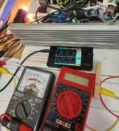
GGridWorks Green Solar replied to the thread New no battery pure sine wave solar power system with smart switchers..Going to bench test with battery power driving transformers and getting the best sine wave output possible, May end with another dual...
-
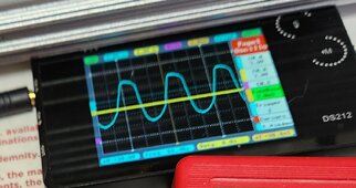
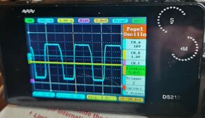
GGridWorks Green Solar replied to the thread New no battery pure sine wave solar power system with smart switchers..Think I may have in the quest for the most power output from the two FET inverter got away from the best sinewave that the ISO...
-
-
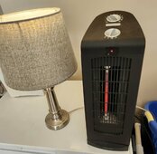
GGridWorks Green Solar replied to the thread New no battery pure sine wave solar power system with smart switchers..Just completed 140VDC dual solar testing on the new two FET inverter survived it all. Mixed results from testing: Ran level 1 quartz...
-
-
GGridWorks Green Solar replied to the thread New no battery pure sine wave solar power system with smart switchers..Starting the preparations for another two FET inverter test. Featuring : Dual 140VDC solar input, much better optic coupler/FET...
-
GGridWorks Green Solar replied to the thread New no battery pure sine wave solar power system with smart switchers..WOW Fixed it 😍 Runs stable pure sine on the two FETinverter, little capacitor across the center of the three 820 ohm resistors that...
-
-
GGridWorks Green Solar replied to the thread New no battery pure sine wave solar power system with smart switchers..Last night did the math on resistors and found out the 50K potentiometers are more than what is needed to cover the optic coupler LED...
-
-
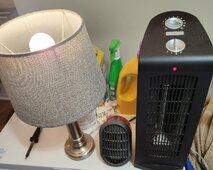
GGridWorks Green Solar replied to the thread New no battery pure sine wave solar power system with smart switchers..Today it's a blue sky day, All three solar arrays running the mini split and more💚 Going to spend some time in making the optic coupler...
-
GGridWorks Green Solar replied to the thread New no battery pure sine wave solar power system with smart switchers..Two FET inverter has been restored to normal operation, in a few days I will test again at 140VDC. Plenty of adjustments to work on...
-
-
GGridWorks Green Solar replied to the thread New no battery pure sine wave solar power system with smart switchers..Final results on 180VDC two FET inverter testing. The inverter operates more stable at dual 140VDC, Needs improvement in the opto...
-
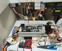
GGridWorks Green Solar replied to the thread New no battery pure sine wave solar power system with smart switchers..Good morning ready for the dual 180VDC testing 6AM, solar day starts around 9AM. First picture two FET inverter ready for...
-
-
GGridWorks Green Solar replied to the thread New no battery pure sine wave solar power system with smart switchers..Tomorrow morning will start 180VDC dual testing on the two FET inverter, P channel Mosfets have arrived, have smooth operation on the...
-
-
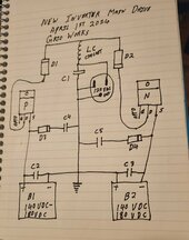
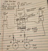
GGridWorks Green Solar replied to the thread New no battery pure sine wave solar power system with smart switchers..⚠️ Caution connect earth ground that appears between B1 and B2 at your own risk, not tested yet and on the surface looks electrically...
-
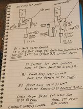
GGridWorks Green Solar replied to the thread New no battery pure sine wave solar power system with smart switchers..All new diagrams once I get it fully functional for now these are the best for getting it done. Read from page 39 on for ongoing...
-
-
GGridWorks Green Solar replied to the thread New no battery pure sine wave solar power system with smart switchers..So much for saving money on the P channel FETs the new FETs are leaking big time at 180VDC supposed to be rated for 200 volts, swapped...
-
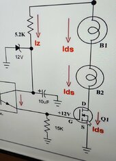
GGridWorks Green Solar replied to the thread New no battery pure sine wave solar power system with smart switchers..The triple 820 ohm resistors accross the 12VDC power supply is working great to provide the second feed to each optic coupler LED...
-
-
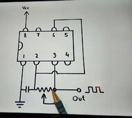
GGridWorks Green Solar replied to the thread New no battery pure sine wave solar power system with smart switchers..Busy recently with yard work and gardening, still fighting P channel triggering from the 555 timer, Going to have to get creative with...
-
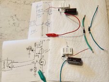
GGridWorks Green Solar replied to the thread New no battery pure sine wave solar power system with smart switchers..Spent the entire day rebuilding the NPN transistor circuit, New resistors connections, worked perfectly in my lap with LED in place of...
-
GGridWorks Green Solar replied to the thread New no battery pure sine wave solar power system with smart switchers..Moved 555 timer to the other end of the inverter, about 6 alligator clip jumpers no longer needed, short direct solder connections to...
-
-
Loading…
-
Loading…
-
Loading…
-
Loading…