diy solar

diy solar

Charge Termination Current at Desired Voltage

Alarchist

New Member
Joined
Aug 15, 2023
Messages
128
Location
London, UK
I often see quoted the standard LFP 0.033C or 0.05C Cell datasheet rate as termination current for fully charged cells.

For EVE 280K: 280A x 0.05 = 14A (@3.65v)
For Gotion 340: 340 x 0.05 = 17A (@3.65v)

Etc.. (I have the Gotion)

This is always specified by Cell manufacturers when charging to 3.65v per cell. However it gets regularly repeated here when charging to only 3.45v per cell.

There was a long rambling thread recently which touched on it: Almost everyone is charging their LFP wrong! - post 69

With references from: https://nordkyndesign.com/charging-marine-lithium-battery-banks/

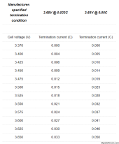
The critical point being that according to Nordkyn Design, we should be adjusting termination current based on termination voltage, not use a set figure for all termination voltages.

Table from the Nordkyn Site:
Termination Condition.PNG

According to the above, if using 3.45v termination voltage we should actually terminate at 0.014C

For EVE 280K: 280A x 0.014 = 3.92A (@3.45v)
For Gotion 340: 340 x 0.014 = 4.76A (@3.45v)

Ok so maybe we want to be careful not to overcharge, and the above table is the cut-off rate that we MUST stop at, but it's also maybe a useful ready reckoner to help know where the tail current cut off absolute point is.

Or is it safer just to ignore it for the minimal extra Ah pushed in and stick to the 3.65v rating?
 
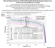
The greater the charging current the higher the cell overpotential voltage bump up required to push the required amount of lithium-ion migration to make the demanded cell current. Cell voltage under charging or load current does not represent its state of charge.

Higher charging current results in more time for charging current taper down when cell approaches full charge. As current tapers down the overpotential voltage bump required is reduced because of less cell current.

Taper off current during constant absorb voltage phase of charging should be ratio'd to the bulk constant charging current rate. Lower charging current should have a lower taper current absorb termination current setting. Should not set absorb termination current taper below about 1% of cell AH rating,

Be careful of charge current level absorb charging phase termination. At lower bulk charging currents, it can result in short absorb phase time periods that does not give BMS time to balance cells. Time based absorb termination is better for lithium-ion battery BMS cell balancing.

LF280 AH battery dischg 0.1C-1.0C.png
 
Taper off current during constant absorb voltage phase of charging should be ratio'd to the bulk constant charging current rate. Lower charging current should have a lower taper current absorb termination current setting.

Nice graphic! Is the ratio here in relation to manufacturers standard charge rate at 0.5C, and the taper termination being at 0.05C? Would that mean a charge rate of 0.2C should have 0.02C taper termination?

3) Charging to a top of 3.5 with your endamps/tailcurrent of 17A is proper & correct, this is a resistance measure as those cells can take 170A when at 0% SOC, as the cells fill-up the resistance increase reducing the charge amperage taken ! 17A charge taken they are technically full.

In most cases I guess the 0.05C taper termination rate (17A for me) is the safest bet, and probably simpler to remember / stick to as a safe principle.

Although the Nordkyn table and RCinFLA point to some good reasons afaiu to lower the taper termination based on a lower absorb voltage than the manufacturer's specified 0.05C @ 3.65v.
 
Ok so maybe we want to be careful not to overcharge, and the above table is the cut-off rate that we MUST stop at, but it's also maybe a useful ready reckoner to help know where the tail current cut off absolute point is.
Yes, You already answered this. You should be confident in your understanding.

Or is it safer just to ignore it for the minimal extra Ah pushed in and stick to the 3.65v rating?
Yep. It will always be favourable to be on the safer side when it comes to things.
Who knows the indicated 3.5 V on the charge controller is actually 3.6 V when measured using a calibrated multimeter

So yes, it always be safer and easier in the long run for your cells to do 0.05 C @ 3.45 V instead of 'pushing it' to 0.014 C @ 3.45 V
 
Last edited:
Based on the actual used charging bulk current rate, you want to make sure taper down absorb exit trigger is not so low that the cell remains at the higher absorb voltage for an extended period of time.

Many chargers that use current level taper down trigger to exit absorb phase also have a secondary timer that sets the maximum amount of time allowed in absorb phase. This is a good failsafe secondary absorb phase exit trigger to prevent never ending absorb phase due to inverter load current keeping charger thinking current taper down has not occurred or a battery that has excessive leakage current.

Most PV charge controllers use timed absorb phase exit, not current taper down absorb exit because their bulk current rate is unreliable due to PV array illumination variance. Significant issue that should be avoided by proper PV charge controller setup is continuous re-bulk cycling to absorb voltage too often.
 
Last edited:
I know this discussion is a bit old it appears there have been at least one other other on a similar topic.

I have been doing tail amp controlled charging on AGM batteries for upwards of a decade, on all three of the charging sources in our camper van. Shore power is fully automatic with a Magnum MS2000 inverter charger, BMS kit, and ARC-50 remote with monitor. Solar is also full automatic with 300 watts of 12v panels and a Blue Sky solar controller. Alternator charging is from dual alternators totally 520amps of capacity and manually disconnecting the coach batteries when they reach the correct tail amps.

I am no in the process of switching to a 618ah lifepo4 bank at 12v with the only change in equipment is the installation of a Wakespeed remote regulator on the alternators so I will be able to do automatic tail amp charging with it just like the other sources do.

Based on the testing I have done to date, which is still a bit limited, tail amp control is the only way to consistently hit a target SOC for the lithium batteries. As others mention, the voltage curve is so flat you just can't do it accurately and repeatedly.

Most here seem to be shooting for quite high SOC at full charge, but I intend to not go that far and will be stopping in the 90% plus a bit maybe range. I also will be using a lower, less damaging according to many sources, voltage at 13.7/13.8 absorption and full cutoff based on tail current.

Based on what I have found learning to hit the 90% range, the tail current needs to be very much higher than the ones listed above or in other discussions. I am determining the estimated SOC using the rested voltage of the bank after sitting overnight disconnected after charging as that give a fairly close determination, especially for consistency testing. When done I will confirm with a drawdown capacity test.

I ran a test today at 13.8v absorption and a .1C amps tail current end of charging settings. It appears that it is going to settle rested at 13.34v which depending on what chart you use is over 95% so 60 amps is a bit too low. It had probably 20 minutes of tapering from the constant current .2C amps charge rate I was using so quite a while after the knee started. I noticed during the test that the 120 amps was easily achievable at 13.7 or maybe even 13.6v absorption so I will try that tomorrow. Lower voltage charging is currently being touted as a life extender of significance if you can get the results you need that way. I will probably move the tail current charge termination up to 80 amps to see how that goes. Luckily, the Wakespeed charging can be altered very easily with their phone app, so even when we go out camping a 10 minute configuration change can be done anywhere we happen to be. I am sure we will continue to narrow down the window for consistency over time.

My guess is that all the very low tail currents listed are because of the high voltages used and the desire to get to 98+% SOC range. If you don't need that much SOC for your system to operate effectively, cycling mid range will likely give much longer life, at least based on the data I have found lately. A couple of years ago it was charge 14.4v and hold for "x" amount of time or even float there but many are now at 14.1 or 14.2v and some listing "gentle" lithium charging at 13.8v or so. Same with charge rates, as when all the lithium stuff started they were talking charging at 3C rate, now a lot of them are in the .2-.4C range. The specs are very, very quickly getting more conservative now that the manufacturers have had product out long enough to start seeing failures and it appears they are trying to reduce the failure rates and add life.

We have more capacity than we normally would use in even a week of no charging at all at 618ah so our intent is to charge almost all the time with the alternators and never use shore power or solar. We should be able to operate in the 30-85% range nearly all the time once I get the battery monitor auto calibration numbers set properly so we can go by AH down to know where we are related to our not really full high starting point for SOC.

Pretty interesting and fun project to get all the kinks and blending of existing equipment into the new technology batteries, and to make it easy to use on the road.
 
Exiting absorb charging cycle via tail current taper off is a good method of indicating full state of charge but is not usually done for solar PV charging. For PV charge controller a fixed amount of absorb time is set to exit elevated absorb battery voltage phase of charging, typically 30 mins to 2 hours of absorb time.

Reason for this is solar PV is unreliable for providing a consistent charging current and a cloud going by may be misinterpreted as a current taper down by charger causing charger to prematurely drop to float state of charging.

Second issue is to avoid constant recycling to charging absorb phase. It is hard on any battery but especially degrading for LFP cells. You have to set battery voltage level to trigger a re-bulk charging cycle. PV controllers have a requirement of having a minimum battery voltage for a period of time to allow a timed lockout period to prevent re-bulking too often.

Some chargers are fixed and will reinitiate a re-bulk charging when an inverter load drags down battery voltage for a short period of time.
 
Why did this thread not gain any traction? I was super interested in hearing about opinions of top balancing to 3.425 amps instead of 3.6
 
Back
Top