diy solar

diy solar

JK BMS WIRING

raffy323232

New Member
Joined
Apr 10, 2024
Messages
5
Location
MANILA, PHILIPPINES
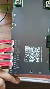
good day to all. just bought the new jk bms. 16s 150amps with 2amps active balancer.
my question is... why there is 2 "B8" Terminals. which one should i use?
and is the first red wire from below will connect to main negative terminal?


thanks to all....
 

Attachments

  • 434156454_439854461893855_9192323136078154940_n.jpg
    434156454_439854461893855_9192323136078154940_n.jpg
    99.1 KB · Views: 33
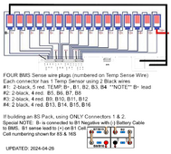
Here is a link to the description and wiring diagram found on the JK BMS website. Its a little blurry but looks like the B8 pin next to NT3 on the 3rd connector is not used. Just leave that particular red wire disconnected.

 
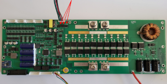
On mine both paths have the resistor in place so either could be used, other boards only have the resistor on the early path. Look above the 5th 8 pin chip in from the top left and you can see the unpopulated position for the 2nd R01 resistor, no other 8 pin chip is fed from 2 pins.
 

Attachments

  • BMS Borad pic from internet.png
    BMS Borad pic from internet.png
    2.4 MB · Views: 13
On mine both paths have the resistor in place so either could be used, other boards only have the resistor on the early path. Look above the 5th 8 pin chip in from the top left and you can see the unpopulated position for the 2nd R01 resistor, no other 8 pin chip is fed from 2 pins.
thanks!...i wonder whats the point of the manufacturer of this bms in creating this confusion on B8 terminal
i have another question... will my bms be destroyed if i connect the B8 on the leads without that resistor?
 
Last edited:
thanks!...i wonder whats the point of the manufacturer of this bms in creating this confusion on B8 terminal
i have another question... will my bms be destroyed if i connect the B8 on the leads without that resistor?
No, it will report a cell count issue and throw an alarm but no damage. Your JK reported total voltage will be short by the missing cell.
 
I took JK's image, sharpened it and added clarification which should be there by default.
Before anyone asks... I will not be editing or reviewing their materials/manuals or guides again. This image is only to support our fellow members.Wrire-Diagram (ENH).png
 
Last edited:
What if you use both B8 wires on the B8 terminal? Like in the picture. A guy told me it's fine and he been using it that way.
 

Attachments

  • Messenger_creation_eea7fde7-e551-4e3f-abf5-01c81f960be1.jpeg
    Messenger_creation_eea7fde7-e551-4e3f-abf5-01c81f960be1.jpeg
    161.5 KB · Views: 4
What if you use both B8 wires on the B8 terminal? Like in the picture. A guy told me it's fine and he been using it that way.
Using both to the one cell would share the current so no issue other than the two 2.5A resistors mean you would need 5A total for one to blow followed quickly by the other. I would only use one as you lose the 2.5A protection using 2 wires.
 
Back
Top