diy solar

diy solar

re powering an older e-bike

Wiley

New Member
Joined
Sep 21, 2019
Messages
73
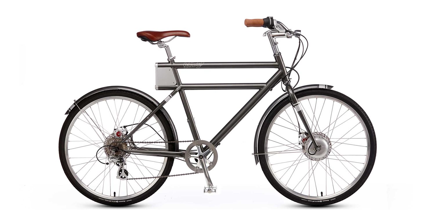
I recently acquired a Faraday Porteur S with what I suspect is a dead battery. These bicycles were the result of a Kickstarter startup which went out of business few years ago. The original battery was built of 18650 cells and were internal to the down tube of the bicycle frame. Replacement batteries are no longer available. The bicycle has a 36 volt 250 Watt motor (a 8Fang Chinese built) on the front hub. These motors are commonly over driven to get more power. My "cunning plan" is to re power with three 12 volt LiFePo batteries each with 15Ah capacity. These would be wired in series to achieve the 36 plus voltage. These LiFePo batteries are quite small and would be contained in a small pack on the rear bicycle rack. The original range was listed as 15 miles when traversing small hills and 20 miles for flat land travel. That's with the 43 volt 5.3 Ah battery. By increasing the Ah I expect (hope) to dramatically increase the range. I want to use three 12 volt batteries in order to be able to charge them using a small dedicated solar array straight from panel to controller to these batteries rather than including a larger array with controller to battery bank to inverter to charger to these batteries.
I find several brands available with these small Ah rating (all of course, Chinese manufacture) and wonder if anyone here has experience with or can recommend a brand.
Also thoughts/suggestions welcomed. Thanks, Wiley
 
Can't help you there, but if you'd rather get an ebike battery off the shelf, 36v and 48v ebikes are pretty standard these days.
Yes, you'll get a lot more range with that setup.
 
First I would figure out which Bafang/8fun hub motor you have.

Then which controller you have. You may need to upgrade the motor controller to go to higher voltage, but the rule of thumb is that you can USUALLY overvolt by 1 step. Meaning 24v can run at 36v, 36v controllers can run on 48v and so on.

If your hub motor can handle it I would be looking for 48v-52v battery as they are more common.
I wouldn't use 12v in series on an e bike, too much to go wrong.

Something like this would probably give a nice range. I know nothing about it personally but it looks pretty universal.


If you want to charge it with a solar setup you'd need about 4 panels in series and a 48v Solar charge controller. No need to mess with inverters or other banks. If you want to keep the array small you can use 25w panels in 4s configuration for 2A charging in full sun. Step up to 4 100w and the SCC will be limiting current to the set point on all but the most overcast days.

The Victron 100/20 MPPT Smartsolar that is perfect for such things. You can dial in the exact voltage you'd like and limit the amperage. This controller can be unhooked from the battery while the panels stay attached without hurting anything. They reduced the price a while back and they now cost $90. It has a great bluetooth app so you can check progress from your phone. I wouldn't use anything else, as I haven't seen anything better for less.
 
rather than including a larger array with controller to battery bank to inverter to charger to these batteries.
You can get a genesun solar charger at whatever voltage you want.

These are super small, light, and awesome. You would probably select the custom voltage option. The link is for the boost converter. You would only use this with a PV array at LESS than you battery voltage. I use mine with a 36v array to charge my ebike battery to 58.8.

Were you planning on individually charging the 12v batteries one by one?
 
First I would figure out which Bafang/8fun hub motor you have.

Then which controller you have. You may need to upgrade the motor controller to go to higher voltage, but the rule of thumb is that you can USUALLY overvolt by 1 step. Meaning 24v can run at 36v, 36v controllers can run on 48v and so on.

If your hub motor can handle it I would be looking for 48v-52v battery as they are more common.
I wouldn't use 12v in series on an e bike, too much to go wrong.

Something like this would probably give a nice range. I know nothing about it personally but it looks pretty universal.


If you want to charge it with a solar setup you'd need about 4 panels in series and a 48v Solar charge controller. No need to mess with inverters or other banks. If you want to keep the array small you can use 25w panels in 4s configuration for 2A charging in full sun. Step up to 4 100w and the SCC will be limiting current to the set point on all but the most overcast days.

The Victron 100/20 MPPT Smartsolar that is perfect for such things. You can dial in the exact voltage you'd like and limit the amperage. This controller can be unhooked from the battery while the panels stay attached without hurting anything. They reduced the price a while back and they now cost $90. It has a great bluetooth app so you can check progress from your phone. I wouldn't use anything else, as I haven't seen anything better for less.
Hi MTM,
Here's a link to what came up when I searched the 8FUN Bafang motor:

https://www.electricbike.com/250-watt-hub-motor/
.Here is a discussion of one person's answer:


The code on my motor is: SYXD01F.
The bike has simple controls and basically no readouts for speed, mileage, battery state etc.
The bike was designed to look like a vintage bicycle as opposed to what is common styling on an ebike today. The motor is designed as an assist to pedaling. Weight of the Porteur S is slightly less than 40 pounds. I really want to keep near that...
I used to tour and the most my kit weighed was 82 pounds (bike 35 lbs, the rest my gear).
Hi Scrotus,
I am sort of thinking of a base camp with a few panels and my small trailer; a couple dedicated panels and perhaps two sets of batteries. One set charging while I'm off plying/exploring with the other. I was actually thinking using Anderson connectors and charging in parallel and running in series. The load is small enough that I figured Anderson connectors would work...?
Thanks for the replies
Wiley
 
That is a neat bike. I would guess that you don't want to overpower that hub motor too much. The fact that it is single speed means that it will easily get bogged down and take lots of battery to keep it rolling. The more you help it along the better, but your starts will be slow with the track bike drivetrain which means a bigger battery will be better for long rides. Keeping the weight down is a good Idea too.

Charging in parallel and discharging in series used to be done in diy setups. I would really try to avoid this.
Hi MTM,
I guess you have guessed this is my first ebike and while I feel at home around most standard bicycles (I have a stand and most of the tools and do all my own repairs/replacements etc. and have an embarrassing number of bicycles) I am low on the learning curve with respect to ebikes.

According to the following articles/links this ebike has a torque sensor as opposed to a cadence sensor. As I understand it this means the harder I press down on the pedals the more power it supplies to the motor. Does the "more power" mean faster? Or does it mean it does more work at a constant speed before stalling?


When you wrote "I would really try to avoid this." would you elaborate? Is there a safety issue?
Bests, Wiley
 
Torque sensing is the better of the two for pedal assist. If done correctly the system should just feel like it is helping you as you pedal. Cadence sensing is just a dumb counter. So many pedal rotations equals x amount of watts to the motor.

With the system on your bike I would guess that it takes a bit of force to get full amperage to the motor. If this is fine for you then I would just keep it this way and get a battery set up so that you can ride it and see if you need to change anything later. Some controllers allow a throttle input so you may be able to add one later if need be.

The lack of throttle was probably a cost cutting/style/EU compliance thing. I think you will find that there are times that a throttle will make more sense to maintain speed without pedalling hard. The best in my opinion is the throttle for when you want it and torque sensing when you don't.

I would avoid parallel charging and series discharging mostly because it is added weight and complexity that you don't need. It also presents a risk that a connection between batteries fails. It is doable, but there are a lot of native 36v and 48v batteries that avoid this issue.

If you could find a Ryobi 40v tool battery and rig it up you could try the bike out and see how you like it. They are actually 36v nominal. It won't have great capacity but it would give you an idea of how the bike functions. There are other tool batteries around that are in the right range for voltage, but I know the 40v stuff is fairly common around here. I would find a battery to try it out with for a couple short rides.

Do you still have the original battery pack from inside the frame or is it gone?
Thanks for the reply MTM,
The battery is still in the bike... Right now it acts "DEAD" which is sort of what I would expect if it was left in storage (which the condition suggests) and so I expect the batteries voltage dropped below what the BMS would recognize. The bicycle looks like it was left in a garage/storage building untended, unused and unloved. Perhaps the previous owner thought it worthless as the company is gone and replacement batteries with them. And so gave it to Goodwill after salvaging the saddle. There was a Allen head screw lost from the rear rack support. The bike looked forlorn and without a charger, Goodwill tagged it at $19.99 and with my senior discount I bought the bike for $16.00 plus tax. I had a Brooks B17 saddle in my parts box and replaced the lost screw. With replacing those and a simple wipe down the bicycle looks much much better.

The bike is outfitted with Schwalbe Marathon tires in near new condition which are worth more than I paid so it really wasn't much of a risk.

You probably saw the original battery pack in the link... it's not designed to be easily accessible or reparable . Likewise the controller is potted and so fine if it works, but like the battery, if it doesn't one replaces with what will work.

I think you are right in suggesting the 40 volt battery as a trial to see what works on the bike... my wife has a string trimmer that uses a 40 volt Li ion battery pack. I'll check the thrift stores for a matching but dead 40 volt tool and salvage the socket so the battery will easily connect. Inexpensive trial but my gut feeling says neglect was the cause of the demise and it is simply a case of dead battery. We'll see.
Thanks, Wiley
 
I would guess that it will work fine once you have a good battery of some kind. That is a very neat frame design. Like you said, $70 + just for those tires. What a find.

You can order 3d printed battery sockets to fit common tool batteries on amazon for $20 or so.

I would also try to find a match to whatever type of connector is used on original battery so that you have no need to cut into the original wiring harness.
 
Wiley,

Kind of in the same place as you are. Picked up my first e-bike Hyper (Walmart special, 36 volt 7.8AH) at a police sale $150 (I need to go to Goodwill more). The battery is dead and locked in.

I was thinking about going the same way as you were thinking by making a better battery, but have not gotten into it as much as you have.

Please keep us/me posted as to how your project is working out so I can follow in your footsteps.
 
Hi Larry,
Will do, although Will may want to move this thread to "Chit Chat" as it seems less solar and more tangential. Our goals are similar. I still wish to end up with a simple, robust and stand alone setup where the battery can be directly charged from a solar panel(s) and controller. There are some distinct advantages to having all systems and run by and off a main solar array and battery bank. However, IMHO having simple separate systems has its own advantages.... the old saw about not having all one's eggs in one basket so to speak. Also I would like to end up with a system that is portable. I don't expect that I will be running off to explore some desert areas like I used to when younger... but I would like the option.

The find at Goodwill was truly a fluke...I haven't seen deals on bicycles since before COVID. Ten years ago one could fairly regularly find deals on really nice and little used bikes there for not much money. I took a pair of bikes and worked them over and my wife and I spent each September for three years touring France and Germany. Total investment (bikes, panniers, locks etc.) was about $150 for each bike. Harder to pull that off now.
Wiley
 
Update:
Written on controller 11/25/17 which either the date of manufacture or date of installation. It would appear the ebike is just over 6 years old. Also the wiring is internal and runs up along side the seat post. The seat post is contained and held in an eccentric tube inside of a tube one would assume to be the seat tube. This eccentricity creates a small 2.25 mm space for the wires on the rear side of the true seat tube. Presently the red and black wires (charging) therein are at that maximum diameter. Wires depart the controller and disappear into a slotted hole and emerging into view thru the access hole as a cable molded into the connectors.

There is a battery connection to the controller below the10 inch length of the internal seat post tube and accessed thru a cutout just above the bottom bracket. The actual connectors there are three pin (battery connection), a five pin (suspected to be battery state/BMS) and a four pin (suspected of being to the torque sensor). All appear to be designed as watertight. I have been unable to find nomenclature or maker for these connectors.

The charger connection is XLR and there is continuity between the #2 pin (usually positive) and one of the three on the lower connectors (between controller and battery) NO continuity between either of the other two and the #3 (usually negative) pin on the XLR. This is using:


I am planning on putting the ebike on the stand and removing the battery. However, at the moment I am looking to borrow a charger prior to removal in a last ditch attempt to see if the battery will charge. Removing/destruction of the battery will ascertain the uses/functions of the other two connectors (4 and 5 pin). However, destruction of the battery will cause the loss of any "Battery State" metering. Going forward.

At present battery shows no voltage. I am expecting to disassemble it to determine correct polarity for the wires. This will also allow additional and continuous wire length as the dissected battery (in links) shows the wires running the full internal length of the battery and termination to the BMS at the distant end. Thoughts?

Bests, Wiley
 
A quick update and a question:
Replacement batteries in the form of three Li Time 12.8 volt 12Ah LiFePo batteries arrived. As they came they measure 14.2 volts each and when in series measure 42.7 volts. IMHO this is close enough to the ebikes original battery voltage of 43.2 volts. The amperage of the original battery was 5.3 Ah and so I expect my replacement lashup to approximately double the range. The weight of the battery package (aluminum cylinder with leads) was 3 pounds 4 ounces and curiously that is the same weight of one of the three LiTime replacement batteries.

I have removed the battery from the bicycle and have managed to remove the shrink wrapped battery package from its aluminum tube without damage. This shrink wrapped package includes the BMS.

The there is a second cable between the battery and the controller. It enters into the shrink wrapped package and goes where I do not know. I expect this provided the state of charge and other information to the controller. The fellow in the links provided above simply used the red and black power wires which attached to the BMS as he damaged the BMS in his disassembly of the aluminum tube/battery. As a consequence the on/off switch for the bicycle no longer worked. The battery pack he used for replacement came with an on/off switch.

My question for those who understand BMSs and their various functions: Can I simply sever the leads to the separate cells from the BMS of the old pack and connect my new battery to old power connections and preserve the on /off function? I realize charging thru the orginal port and state of charge functions etc. will be lost. This maybe one of those questions which cannot be ascertained as this was a designed for this ebike BMS. Does one simply cut the sensing leads to each cell and see what one has left in the way of function. Is there a downside to simply cutting the leads? The controller is unique to the this ebike and I do not wish to damage it.
Many thanks in advance.
Bests,
Wiley
 
One option is to take the existing battery to a Battery Store/ repair shop and have them put in all new 18650 batteries. This is a simple task for a battery enthusiast. 18650 batteries are in everything including the tool 12v battery you mentioned. They are the favorite for Tour de France winners also. they slip a handful of 18650 or 2100 batteries down the seat tube and a motor at bottom of seat tube at the bottom bracket drives the cranks from inside the frame -not a lot of power but enough to make millions winning a race. If you watch the Tour this summer you might see top riders making 4,5 or 6 bike changes. These are $20,000 bikes and should last for year, not just minutes, so they are obviously changing out, not the bike, but the batteries. The officials look the other way like they did with doperLance.

If you measure a 12v tool battery you will likely get more than 12v.
My 18v tool batts give 20 volts, and work just find (with adapter) in 20 volt tools too.
I would use an 18v tool battery instead of little 12v ones.
Look more into your motor and controller, it might handle 36 volts and up to 48. If so then two 18 volt in series (or 20v) will give you 36 (or 40) volts, and it might work just fine. A lot of these bikes are 36 but the system is a 24-48 volt electronics, so can handle a wider range. Some stop at 36 though, so that is why you need to research it.

I am currently adapting two 40v batts to work on a 36 volt motor.
 
Thanks 0truck0 for the reply.
I have the battery out and this is really not a simple case of installing batteries in a plastic frame, welding on some strips of nickel and closing up a case. These cells are grouped in a pattern of three in cross section and eight cells end to end. The cell pattern is such some cells needed to be placed side by side and then the nickel strip welded on and then the cells folded so they were positioned end to end. The assembled batteries were then wrapped in what I think is a dielectric tape (perhaps the tape is for structural integrity as well). This assembly was then shrink wrapped and slid into an aluminum tube of diameter slightly smaller than the inside dimension of the bicycle down tube. The ends of this aluminum tube were sealed and crimped (dimpled). Disassembly required drilling out the dimples and carefully removing the sealed machined ends. I have spent hours carefully undoing/ unwrapping this "mummy". The original battery (when available, which it no longer is) cost $449.99. Which perhaps wasn't so shocking considering what the Panasonic NR cells probably cost back in 2012 (from date on cells).

A surprising thing to me is that the whole package seems to have the fuse as part of it. I thought fuses were to be the weak link to protect more expensive parts from damage in the case of an electrical issue...a blown fuse being cheaper to replace than a controller in this case. But here a blown fuse means replacing the battery, a battery not designed to be rebuilt... IMHO poor design.

But now that I have all this apart I have a question about BMSs and how they (where they) measure voltages. It is my limited understanding that BMS measure the voltages between cells and adjust voltages such that the voltages of the cells are close to one another.

This battery is constructed of 24 18650 cells. They are wired in 12 groups of cells in wired in series with each group being two cells in parallel. There are 12 BMS leads, one connected at every connection between cell groups. So two cells in parallel and an BMS lead two more cells in parallel and another BMS connection and so continuing for the twelve measuring points.

So my question: Is the BMS measuring between the first lead connection and the second and then between the second and the third and then the third and the fourth and so on? Or between the first and the second then the third to the forth...essentially every other cell group...that doesn't make sense to me.

So why do I want to know? I wish to power this ebike via an external battery...the fellow (Darthracing), whom I reference in above links simply clipped the power output leads and attached leads to a new external battery to the power output leads. I can't fault him as the BMS to his battery was destroyed when he attempted to disassemble it. However, the result was the motor turned on when he rotated a pedal but the motor continued to run after the pedal rotation stopped. That problem may stem from a fault in the torque sensor or from the controller from feedback via the data connection cable which no longer connected to the battery. That proposition came from a member on an ebike forum with which I am also exploring this project. I'm trying to fake out the controller by attaching the BMS leads to a separate fixed battery source...basically a few stacked button cells. If they are all reading the same voltage because they are all connected to the same stack of cells there should be no variance in voltages. Of course the external battery has it own BMS.

This whole exercise may all seem a waste to many but there are a significant number of older (as in 12 years being old) ebikes out there which need not be thrown away simply because the battery has gone bad. I mean that may be the case as one reads that many people are basically giving away older Tesla's when they need a new battery because of the high cost of a replacement battery.

Thanks in advance to all the great minds that understand how these work!
Wiley
 
The external battery "pack" should have a BMS in each battery. Don't bother to cobble up something using the old BMS.
 
wme, You are right, but I'm not trying to use the old BMS. And true the new battery power will have it's own.

However, in conversing with others on an ebike forum, it appears that the circuitry I am calling a BMS perhaps does more functions than a simple BMS. On this ebike there is a two position selector providing two levels of PAS (pedal assist). This would be easy to figure if it had a cadence sensor providing two throttle levels where the motor is either on or off, but this ebike has a torque sensor so it was able to vary the amount of assist within each level of desired assist. I'll call it a BMS/Chipset.

From what I have gleaned from the ebike forum the data communication cable provided more than the battery voltage information...there was nothing more than a simple bar level screen indicating the remaining power in the battery...nothing digital or high tech. When Dearthracing simply connected his new power cables to the output wires cut from the BMS/chipset all the additional info previously provided to the controller was no longer available to the controller. Thus nothing concerning an increase of assistance proportional to additional effort from the rider. The motor simply turned on and ran at a given rate regardless of selecter switch position or effort by the rider.

So my thought is to connect my new battery where the old battery ends (+ -) connect to the chipset/BMS and run my new power input thru the BMS/chipset so that if there is some regulation of power it will provide it. My hope is to fool the BMS portion of the chipset into believing there is sufficient voltage (and that everything in the battery is within limits) such that 1) it will not shut the ebike battery and 2) it will allow whatever function or regulation to occur (regardless if that regulation is done in its chipset or in the controller). In order to fool the chipset into believing there is a battery I suggest attaching the BMS monotoring leads to a separate battery. A battery that has no other function than "be measured".

I think I can do this fairly easily. The wiring in the original battery is two 18650 cells in parallel wired in series to another two cells in parallel which is further wired in series to another two 18650 cells... rinse and repeat. The BMS leads are connected at the series junction of the parallel groups of two, each after the other. So the BMS is measuring single cell voltage , but two at a time. To make the fake battery one takes a stack of 3 volt button cells and attaches the BMS measuring leads to small strips of copper between each cell. The 3 volt is low but not enough to shut down the battery. The stack of button cells (I am thinking 2032 cells) does no work and should last a long time, take up little space, weigh little and aren't expensive.
Thoughts?
Bests, Wiley
 
Can you just skip the pedal assist and replace with a throttle?

I think your project is too specific for a solar forum, and the ebike forum will have people who have done similar things instead.

Since you are going external battery then that solves a lot of issues trying to fit something in a tube.
In the end, is this not just an electric motor that you can give voltage to and make it go? Is the motor itself more complicated than voltage in - rotation out?
 
Back
Top