diy solar

diy solar

110V to 220V for mini-split.

JazzRVwSolar

New Member
Joined
Nov 9, 2023
Messages
51
Location
Asheville, NC
We have an RV with 115V inverter. Rather than putting in an addition inverter to produce 220V, I though use 115 to 220V boost. However, the ones I see are 2-wire (L1, Neutral, and Ground). Has anyone done this with any of the mini-spits? I look at the models with high SEER and they seem to have an L1, L2, Neutral, and Ground.

We want to use the 220V because they are the only ones that have the ceiling mount option which is a must. There is no wall room to mount the indoor blower
 
Does this look like what you are looking for Outback power PSX-240
 

Attachments

  • IMG_4184.png
    IMG_4184.png
    193.3 KB · Views: 11
Last edited:
Use an auto-transformer.

at5000.PNG
 
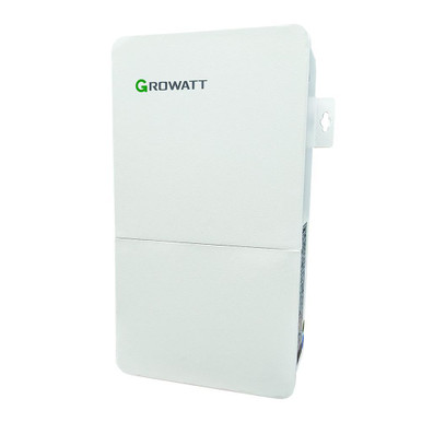
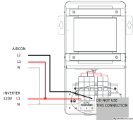
Shows to be for taking 240v inverter down to 120v split phase. Not 120v to 240v from what I'm reading on the growatt unit.
 
Here watch this:
I had already edited it from the part you quoted after looking at the docs. Site wouldn't let me delete the post so I changed it to what it is now.

Still never thought of feeding it like that and the docs didn't show it being used that way.
 
Just keep in mind that the video is incorrect about the phasing. Split-phase is single phase. The two 120v halves are not out of phase. If they were, you would get zero voltage on the two lines.
 
So if you want to feed 240v at 15 amps I going to guess your going to pull 30amps from the 120v source?
 
The video is correct. Two 120V sides are 180 degrees out of phase. If they were in phase you would get 0 volts between them.
I'm Sorry, but you are mistaken.
If they were 180deg out of phase. They would cancel each other out. (Zero voltage)
In phase with each other. The two are additive. (Double the voltage)
FYI: you can't create two phases from one.
A transformer has no timing control. It's just changes the voltage. And the amperage is affected in the opposite.
 
If they were 180deg out of phase. They would cancel each other out. (Zero voltage)
In phase with each other. The two are additive. (Double the voltage)
You are almost grasping this. They try to cancel each other when you connect a load of certain impedance across them. If you were to tie them together you would get them to cancel out creating a short circuit. The only reason current can flow between L1 and L2 is because they are pushing and pulling against each other with each half sine wave cycle.
 
only reason current can flow between L1 and L2 is because they are pushing and pulling against each other with each half sine wave cycle.
L1 and L2 are single phase. L1 to neutral and L2 to neutral are split phase, each 180 degrees from each other. The pushing and pulling is at 60 Hz and a perfect sine wave at 240 volts. What you may be referring to is a 3 wire circuit with a shared neutral which can carry the load of both legs because the neutral sees half the wave cycles of the split phase.
EDIT:
That video which @timselectric posted clarified why the center tap transformer has windings in different directions and why the phase gets 180 degree from the other on the 120 volt legs with respect to the neutral.
 
Last edited:
You are almost grasping this. They try to cancel each other when you connect a load of certain impedance across them. If you were to tie them together you would get them to cancel out creating a short circuit. The only reason current can flow between L1 and L2 is because they are pushing and pulling against each other with each half sine wave cycle.
You have to understand how current flows in a circuit.
I think that this will help you understand.


L1 and L2 are single phase. L1 to neutral and L2 to neutral are split phase, each 180 degrees from each other. The pushing and pulling is at 60 Hz and a perfect sine wave at 240 volts. What you may be referring to is a 3 wire circuit with a shared neutral which can carry the load of both legs because the neutral sees half the wave cycles of the split phase.
That's not it, either.
Watch the video I just posted above.
 
That's not it, either.
I did watch the video but maybe I did not explain it well. The video made it clear that the 240 volt legs are single phase and the 120 volt legs are split because the windings are in opposite directions for L1 to N and L2 to N. That is why a 3 wire circuit can share a neutral without the neutral being overloaded.
 
I did watch the video but maybe I did not explain it well. The video made it clear that the 240 volt legs are single phase and the 120 volt legs are split because the windings are in opposite directions for L1 to N and L2 to N.
I'm not sure how you got that from the video.
It's the opposite of what was explained.
The windings are wound in the same direction.
 
I'm not sure how you got that from the video.
At 1:31 in the video he explained how split phase works when the lower windings are in opposite direction from the upper windings. He used the term, "out of phase with each other". Earlier at 1:25 he described how both 120volt legs would be in phase if all the windings were in the same direction. In both cases the transformer is center tapped.
EDIT: I thought the DC battery illustration was confusing because in that example the neutral carried double the current but that is not how it works in a 3 wire shared neutral AC system in North America.
EDIT2: I watched to the end and he clarified that the windings are in the same direction but look out of phase with respect to the neutral. At least my understanding of 3 wire shared neutral is correct.
 
Last edited:
I see where confusion is coming from. The guy in the video is calling 2 transformer windings being in phase but if your were to take a reference point in the middle of them and then measure voltage waveforms at opposite ends in relation to the middle they would look 180 deg out of phase. Too bad he did not demonstrate it with a scope.
 
Back
Top