diy solar

diy solar

18 month DIY project finally done: 39kW inverter power off grid system

fmeili1

Solar Enthusiast
Joined
Jan 19, 2022
Messages
341
Location
Arizona, Mohave County
Finally after 18 month I've completed the installation of my DIY off-grid system. It was an incredible amount of work, much much more than previously expected.

Tomorrow will be the final inspection of the cities building division and on Friday the inspection of the power company - I'm very nervous...

Here are the key points:
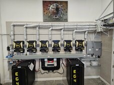
  • Single family home with 200A service and about 2100sqft living space, attached 2 car garage and RV garage
  • Central heat pump for cooling and heating, everything electrical, no natural/propane gas, no wood fireplace
  • Off-grid system with 39kW inverter power, grid only as backup if really required (disconnected most of time via remote controlled contactors).
  • Permission to treat it as a "generator solution" with a manual transfer switch and I have the permit to have a permanent AC-in connection to the grid, independent of the transfer switch position!
  • 18.5kWp solar bifacial modules 460Wp, 40 PV modules organized in 8 strings, strings with 4, 5 and 6 modules in series (no parallel modules), most modules on concrete tiled sloped roof (8 on RV garage flat roof), PV module orientation is 17x south, 11x north, 6x east, 6x west (not ideal roof for solar).
  • LFP batteries (40kWh are allowed, organized in two separate racks)
  • Emergency shutdown features for many possible failure scenarios
  • Fully integrated in existing smart home to implement "smart" energy management and remote monitoring/controlling
20240423_075353.jpg

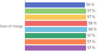
For final testing, I've used the system for the last 5 days and everything is working so far as hoped. The batteries have about 63% SOC remaining in the morning before new solar production begins (this will change in summer for sure). Between 11am and 12pm the batteries are fully re-charged.

Because of the implemented ducted mini spit the AIO's running very nice cool and because of the modded fans, they are really quiet now.

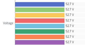
The next charts showing an example of a 24h cycle while testing (full PV production between 6:30am and about 12pm until the batteries are fully re-charged):
1713885499407.png

1713885527905.png

1713885548136.png

Load and consumption situation of the house:
  • 21,000kWh per year consumption
  • 114kWh highest peak consumption per day (usually end of July or beginning of August)
  • Highest consumption between May and August (2,000kWh to 3,000kWh per month)
  • High power consumption devices sorted by power
  • Central heatpump: 5,800W (max. 7kW, <=15kW inrush)
    ▪ Dryer: 5,200W
    ▪ Water heater: 4,470W
    ▪ Wall oven: 3,500W
    ▪ Coocktop large field: 3,300W
    ▪ RV garage mini split: 2,500W
    ▪ RV parked in the driveway: 2,000W
    ▪ Microwave: 1,700W
    ▪ Coocktop 3 small fields: 3x1,400W
    ▪ Washer (front loader with heating element): 1,200W
    ▪ Pool pump: 1,200W
  • High energy consumption devices sorted by runtime:
    ▪ Pool pump: 8 hours only on daytime
    ▪ Central heatpump: in high summer days it runs about 60%-90% of the time constantly (60% at night), in winter time it runs about 20%-30% of the time
  • Power requirements so far:
    ▪ house idle consumption is about 500W
    ▪ AIO idle/self consumption is about 550W for all six units
    ▪ while pool pump is running 8-9h over the whole day the base house load is about 2000W total
    ▪ never seen more than 24kW power consumption at a time – but it may happen
    ▪ possible worst case could be: 2000W idle with pool pump + 5000W heatpump + 4500W water heater + 3500W oven + 6500W for 3 coocktop fields + 200W dryer + 2500W RV garage mini split + 2000W RV in driveway connected to the house + 1200W washer = 32.5kW is still below rating of 39kW with reserve for e.g. toaster, water cattele, microwave, tools, etc.

Unexpected challenges / missed considerations while building:
  • AIO's were extremely loud (our master bedroom is located behind the inverter wall), so I had to modify the fan control of all 18 fans in all 6 AIO's to enable a temperature controlled fan speed. Because they heat up quickly under charging conditions, I had to implement an active equipment cooling on top of this to make them really quiet. To achieve this, I've installed a 9,000 BTU ducted mini split which cooling power is controlled via smart home rules, depending on the AIO temperatures. Now they are usually around 50-52°C, even under high load (charging and inverting).
  • I've implemented an emergency shutdown circuit (I wanted to have that to be able to sleep with a better feeling) which shutdown the system in case of smoke detection or too high AIO temperatures or too high battery temperatures or camera detects fire or manually remote if I want. In case of an emergency is detected, the PV modules are shutdown via TIGO module level PVRSS, the batteries are disconnected from the AIO's via 600A relays, the AC-in's are disconnected from the grid via contactor if connected (usually the are always disconnected anyway). Because these three different types of disconnect's are NO (normally open) operated, I've needed to build a blackstart UPS to initially startup the system.

I am totally amazed and very pleased that my LED pulsing/flickering problems are completely gone - without doing anything! While in building phase, I've noticed the LED pulsing problem a couple of times and I thought many hours about how to solve it. I have no idea why this problem completely disappeared, independent if solar production or not, clouds or not, battery charging or discharging, high or low load,...

I'll update this thread from time to time with new pictures, findings, data, issues, etc.
 
I am totally amazed and very pleased that my LED pulsing/flickering problems are completely gone
Did you do firmware updates? Maybe they are unstable under really light load, and now that your baseline 500W load is on, they are stable?
 
Finally after 18 month I've completed the installation of my DIY off-grid system. It was an incredible amount of work, much much more than previously expected.

Tomorrow will be the final inspection of the cities building division and on Friday the inspection of the power company - I'm very nervous...

Here are the key points:
  • Single family home with 200A service and about 2100sqft living space, attached 2 car garage and RV garage
  • Central heat pump for cooling and heating, everything electrical, no natural/propane gas, no wood fireplace
  • Off-grid system with 39kW inverter power, grid only as backup if really required (disconnected most of time via remote controlled contactors).
  • Permission to treat it as a "generator solution" with a manual transfer switch and I have the permit to have a permanent AC-in connection to the grid, independent of the transfer switch position!
  • 18.5kWp solar bifacial modules 460Wp, 40 PV modules organized in 8 strings, strings with 4, 5 and 6 modules in series (no parallel modules), most modules on concrete tiled sloped roof (8 on RV garage flat roof), PV module orientation is 17x south, 11x north, 6x east, 6x west (not ideal roof for solar).
  • LFP batteries (40kWh are allowed, organized in two separate racks)
  • Emergency shutdown features for many possible failure scenarios
  • Fully integrated in existing smart home to implement "smart" energy management and remote monitoring/controlling
View attachment 211059

For final testing, I've used the system for the last 5 days and everything is working so far as hoped. The batteries have about 63% SOC remaining in the morning before new solar production begins (this will change in summer for sure). Between 11am and 12pm the batteries are fully re-charged.

Because of the implemented ducted mini spit the AIO's running very nice cool and because of the modded fans, they are really quiet now.

The next charts showing an example of a 24h cycle while testing (full PV production between 6:30am and about 12pm until the batteries are fully re-charged):
View attachment 211060

View attachment 211061

View attachment 211063

Load and consumption situation of the house:
  • 21,000kWh per year consumption
  • 114kWh highest peak consumption per day (usually end of July or beginning of August)
  • Highest consumption between May and August (2,000kWh to 3,000kWh per month)
  • High power consumption devices sorted by power
  • Central heatpump: 5,800W (max. 7kW, <=15kW inrush)
    ▪ Dryer: 5,200W
    ▪ Water heater: 4,470W
    ▪ Wall oven: 3,500W
    ▪ Coocktop large field: 3,300W
    ▪ RV garage mini split: 2,500W
    ▪ RV parked in the driveway: 2,000W
    ▪ Microwave: 1,700W
    ▪ Coocktop 3 small fields: 3x1,400W
    ▪ Washer (front loader with heating element): 1,200W
    ▪ Pool pump: 1,200W
  • High energy consumption devices sorted by runtime:
    ▪ Pool pump: 8 hours only on daytime
    ▪ Central heatpump: in high summer days it runs about 60%-90% of the time constantly (60% at night), in winter time it runs about 20%-30% of the time
  • Power requirements so far:
    ▪ house idle consumption is about 500W
    ▪ AIO idle/self consumption is about 550W for all six units
    ▪ while pool pump is running 8-9h over the whole day the base house load is about 2000W total
    ▪ never seen more than 24kW power consumption at a time – but it may happen
    ▪ possible worst case could be: 2000W idle with pool pump + 5000W heatpump + 4500W water heater + 3500W oven + 6500W for 3 coocktop fields + 200W dryer + 2500W RV garage mini split + 2000W RV in driveway connected to the house + 1200W washer = 32.5kW is still below rating of 39kW with reserve for e.g. toaster, water cattele, microwave, tools, etc.

Unexpected challenges / missed considerations while building:
  • AIO's were extremely loud (our master bedroom is located behind the inverter wall), so I had to modify the fan control of all 18 fans in all 6 AIO's to enable a temperature controlled fan speed. Because they heat up quickly under charging conditions, I had to implement an active equipment cooling on top of this to make them really quiet. To achieve this, I've installed a 9,000 BTU ducted mini split which cooling power is controlled via smart home rules, depending on the AIO temperatures. Now they are usually around 50-52°C, even under high load (charging and inverting).
  • I've implemented an emergency shutdown circuit (I wanted to have that to be able to sleep with a better feeling) which shutdown the system in case of smoke detection or too high AIO temperatures or too high battery temperatures or camera detects fire or manually remote if I want. In case of an emergency is detected, the PV modules are shutdown via TIGO module level PVRSS, the batteries are disconnected from the AIO's via 600A relays, the AC-in's are disconnected from the grid via contactor if connected (usually the are always disconnected anyway). Because these three different types of disconnect's are NO (normally open) operated, I've needed to build a blackstart UPS to initially startup the system.

I am totally amazed and very pleased that my LED pulsing/flickering problems are completely gone - without doing anything! While in building phase, I've noticed the LED pulsing problem a couple of times and I thought many hours about how to solve it. I have no idea why this problem completely disappeared, independent if solar production or not, clouds or not, battery charging or discharging, high or low load,...

I'll update this thread from time to time with new pictures, findings, data, issues, etc.
Nice! Are those air ducts removing hot air or suppling cold air?
 
Very nicely done. Seems like you engineered yourself a great system.
 
I think these are down-flow cooled ejecting air at the bottom sucking in at the top, so I bet it's cold air supply with those fancy little air dams to deflect the incoming cold are into the intakes.
Indeed, I missed the fact that that inverter draws cold air in at the sides of the top and exhausts at the bottom (and bottom sides?)
 
What a fantastic intro to a build thread. Makes sense that you too, are a desert rat. Best of luck with the inspections this week
🍻
 
The 18k was not available 18 month ago. I hope I will not regret to choose the EG4-6500EX because it's sunset now. But they are working great so far and it was (at this time) an unbeatable price for a 6,500W inverter, 6,500W AC charger and 8,000W PV with 500Voc and two MPPT's. I would have loved to use Victron components (I'm using them in my RV) but it would have been much more expensive.

All AIO's are running at the latest firmware (DSP=79.71 and MCU=61.13) since it's available. The flickering in the early test phase also occurred with the newest firmware versions. Maybe as @wpns mentioned, it's because the base load is now a bit higher (the 9,000BTU minis split is now always running). Btw. Because the city required to install a 2-pole transfer switch (they didn't allow a previous planned 3-pole TS), I'm running with common neutral setup (program 42 set to ENA to disable the internal N-G-bonding relays) and the bonding screws are inserted in all six AIO's.

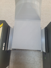
The AIO's are sucking cold air on the top side entries and blow the hot air out on the bottom and bottom side outlets - which is silly engineered because it would create a thermal shortcut. The hot air is rising and get sucked in at the top to cool the device - with this nonsense the AIO's are heating up very fast - whatever they smoked while they engineered the cooling system, they should smoke less of it ;) That's the reason why I've 3D printed these 45° windshields which are installed between each AIO and on the outer ones so the hot air will at least be separated a bit from the cold air.

Here are some more pictures in detail:

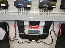
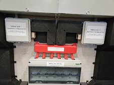
These small grey rectangle boxes (over the pos. busbar and below the wireway) are the two 600A/80VDC relays to disconnect each server rack from the positive busbar in case of an emergency.
20240423_075455.jpg
20240423_075553.jpg

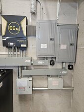
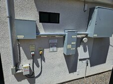
Here are the AC-out combiner panel and AC-in panel with surge protectors below both of them. The left metal box contains the 8 double pole PV breakers. The right plastic box contains the two 3-pole 110A contactors to connect the grid with the AC-in's of the AIO's - but only if really required. I found out that if the AIO's are permanently connected to the grid, each unit will draw about 50W from the grid, even if grid is not used! In my case this would have been 300W permanently drawn from the grid, just to be prepared to use it - I don't want this! Maybe I need 5-10 days per year with some hours grid support and I don't want to waste more than 2,600kWh per year. Instead I've implemented a smart home rule which only closes the AC-in contactors if required and before I initiate the AIO's program 12 "point back to utility" by adjusting this setting. After I will have enough solar again, I will initiate program 13 "point back to battery" by adjusting the voltage value via a smart home rule. While system is on grid, I've reduced the battery charging to the lowest possible value (2A per unit) because I don't want to charge the batteries from the grid.
20240423_075507.jpg

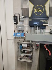
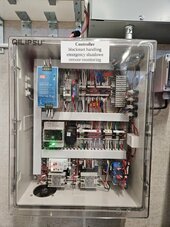
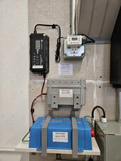
This picture shows the controller which implements the blackstart, the emergency control and the monitoring via SolarAssistant (via MQTT bridge to the existing smart home). Above the controller are the three components for the online-double-conversion-UPS (small inverter, small battery, small battery charger). This UPS has enough power to drive the controller with it's relays/contactors etc.
20240423_075522.jpg
20240423_075534.jpg
20240423_075541.jpg

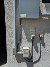
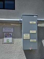
The following picture shows the outside wall with the Tigo RSS transmitter with the two emergency shutdown buttons (the left will disconnect the PV modules via Tigo, the batteries and the AC-in) and the right button just the PV modules via Tigo but the inverters will still running from batteries in this case). Left of the main service panel is the transfer switch. The completely oversized box above the main service panel is just a box to splice the grid to the AC-in breaker panel and the transfer switch (this box and the transfer switch were the only parts which I've not installed by myself, it was done by an electrician).
20240423_115712.jpg
20240423_115723.jpg
20240423_115728.jpg
 
Last edited:
Overkill is underrated. 😁
I've promised my wife that she will not have comfort loss and she does not need to depend on sunshine to do what she wants to do (cooking, laundry, etc.). Also I didn't want to tell her things like "please turn off the oven because I need to use my miter saw.., etc.". For me it was clear that I need to massive oversize the system to have enough reserve to make it unaware, that the house is running on off-grid inverters only from solar and batteries. But because of the price of AIO's and batteries (and in our >300 sunny days location) it's possible without breaking the budget.

A local solar company offered me a system with same PV power, 25kW inverter power and 25kWh batteries for $120,000 (but hybrid) - with the same inverter power and battery size he mentioned between $150,000 and $170,000. I've paid about 1/3 of this and got the 30% federal incentives - so I hope in <10 years it will be paid.
 
Does code allow a battery rack to block an inverter? I know there is something regarding the ground space near an electrical panel but not sure about inverters.
 
The AIO's are sucking cold air on the top side entries and blow the hot air out on the bottom and bottom side outlets - which is silly engineered because it would create a thermal shortcut. The hot air is rising and get sucked in at the top to cool the device - with this nonsense the AIO's are heating up very fast - whatever they smoked while they engineered the cooling system, they should smoke less of it ;) That's the reason why I've 3D printed these 45° windshields which are installed between each AIO and on the outer ones so the hot air will at least be separated a bit from the cold air.

Intuitively it seems stupid, but it's not. Natural convective flow due to heating is very slight and overpowered quite readily by forced convection, i.e., it's 99%+ as effective in downflow as it would be in upflow. There were likely other design factors that made this scheme more desirable than upflow.

There are millions of 04-09 Prius on the road using downflow cooling systems for their hybrid batteries, and they are notably more effective than later designs that are upflow (2010+).

Your little windshields actually do double duty. In addition to the deflection, you get a partial plenum of colder air at ever so slightly higher pressure near the intakes. After inspection, I'd be inclined to get more aggressive with them - maybe even terminate those ducts in "T"s and elbows to ram it straight in... :)

Nice work!

This picture shows the controller which implements the blackstart, the emergency control and the monitoring via SolarAssistant (via MQTT bridge to the existing smart home). Above the controller are the three components for the online-double-conversion-UPS (small inverter, small battery, small battery charger). This UPS has enough power to drive the controller with it's relays/contactors etc.\
View attachment 211126

That little blue box warms my heart.
 
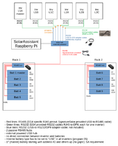
I've used individual communication between SolarAssistant and each inverter with 6 individual RS232 cables. In case only the master inverter would have been connected to SA, some individual AIO values are missing (e.g. temperature, etc.).

Because I'm not using closed loop communication (by intention!) I've connected any battery individually via RS485 hubs to SA. But anyway, SA would not be able to access the batteries if EG4 closed loop communication would be used (it's documented in SA manual and it has to do with SolarAssistant supports only the default protocol and not the "address 1" protocol and for that the first/master battery has to start with address #2). Btw. I remember someone in the forum managed to solve this problem.

I would not have used closed loop communication, even if SA would support it, because of the following reasons:
  • I have control over and would like to know the max. charging current via settings for the bulk charging phase
    • In case the BMS would select this value (which happens in closed loop communication), you don't really know the current selected values and when it changes and why - the value of program 02 (max. charging current) will not show the current selected value if BMS takes control!
  • The supposed disadvantage to rely on voltage instead on SOC for settings 12 "point back to utility" and 13 "point back to grid" is in my opinion not a real disadvantage. The usually very flat LiFePO4 voltage curve gets steeper at very low and very high SOC's and these are the ranges where these two settings usually be used and here the voltage is good enough as an indicator when to switch.
  • Additionally I control the settings for 12 and 13 via smart home rules to force a mode change. In case the combination of the SOC and the corresponding battery voltage would drop below about 8% (I still get the exact SOC values into my smart home system from the batteries, even without closed loop communication) the AC-in contactors will be closed and a minute later the value of program 12 will be adjusted to the highest value to initiate the AIO's grid/bypass mode. After enough solar production begins and charge rise to 12% the value of program 13 will be set to the lowest possible value to initiate the AIO's to switch back to solar/battery mode. After the smart home detects the mode switch, the AC-in contactors will be disconnected again. This reduces the time the AC-in's are connected to the grid to a minimum.
  • In case the batteries would not often gets fully charged, the SOC reading inside the batteries get's fast very inaccurate and I will not rely on it exclusively - that's the reason why the smart home rules use both SOC and voltage to control the mode switching!
  • I very often read about closed loop communication problems and it heavily relies on firmware of AIO and batteries, additional wiring with possible problems, etc. that's one reason more for me to not use it. In my opinion, the closed loop communication is overrated - but I may be wrong.

For more details, you may follow this thread.

1713918194495.png

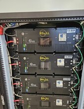
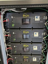
I have a mix of EG4-LL (V2) and some newer EG4-LL-S batteries and the SOC's and voltages are very close. Luckily I also have very low cell voltage delta on all batteries (I transfer the highest and lowest to the smart home and calculate the deltas there, SA is only able to get the highest, lowest and average but not all individual cell deltas). In case some of the parameters will go out of specific limits, I will receive messages on my smart phone (via OpenHAB's Telegram and WhatsApp bindings/bridges). If some of the values like temperatures, voltages, etc. will go really crazy, the emergency shutdown will be initiated - but before I will be informed to be able to intercept.

20240423_175610.jpg 20240423_175543.jpg

1713920739320.png 1713920763580.png
 
Last edited:
Intuitively it seems stupid, but it's not. Natural convective flow due to heating is very slight and overpowered quite readily by forced convection, i.e., it's 99%+ as effective in downflow as it would be in upflow. There were likely other design factors that made this scheme more desirable than upflow.

There are millions of 04-09 Prius on the road using downflow cooling systems for their hybrid batteries, and they are notably more effective than later designs that are upflow (2010+).
That's interesting news for me - maybe the engineers are not as crazy as I thought... but even if the hot air gets sucked out of the bottom, they should have done something to prevent a thermal shortcut (but I don't know how). With the original design and without active cooling, the devices become significantly hotter than would be the case with reverse air flow.
Your little windshields actually do double duty. In addition to the deflection, you get a partial plenum of colder air at ever so slightly higher pressure near the intakes. After inspection, I'd be inclined to get more aggressive with them - maybe even terminate those ducts in "T"s and elbows to ram it straight in... :)

Nice work!
Thanks. My first idea was to inject them right into the inlet with these 3D printed adapters which I've tested. But I found out that there is nearly no difference to the current selected method to just let the cold air fall into the 45° shield. Also the AIO filters are better reachable without these adapters.
1713922071150.png
That little blue box warms my heart.
:) (y)

Update:
Btw. I noticed something unusual about the AIO's temperatures. 2 of the 6 units getting a lot hotter compared to the other 4 and I have no idea why (between 4-8°C which is a lot). So I was forced to re-wire my PV strings to let the 2 hottest units only serving one PV channel with the lowest PV wattage to smoothen out the temperature differences. I have no idea why they are running hotten (manufacturing tolerances?) but I've double checked the outside case temperature with a thermal camera and on the outside they running about 2°C hotter compared to the others. There may also be an inaccuracy in the temperature measurement inside the unit... but anyway, now the all run with about the same temperature in usual condition.
 
Last edited:
Back
Top