Srp does not have a limit, just limits how much they pay for any excess productionIf you want to stick with Tesla/Enphase then there are other options, like a generation panel with a 200A main and 200A subfeed (back to all your existing loads) that all your solar and battery tie into. That panel can have a 400A bus and not require major re-work. At 21.5kW of PV though the utility might have some issues; most states limit you to <~16kW grid tied.


You are using an out of date browser. It may not display this or other websites correctly.
You should upgrade or use an alternative browser.
You should upgrade or use an alternative browser.
400a main panel needed?
- Thread starter Subestile
- Start date
zanydroid
Solar Wizard
Sounds like the breakeven/return wasn’t there with the correct model.I never would have done solar initially
1) how was their model wrong?
2) how are you preventing the same mistake from being made/changing the economics so adding more is more viable. An answer here could be to save money via DIY. But if ROI is tight on a turnkey installation for your site conditions you should be scrimping more right now, like considering the non Enphase options.
Without answers to (1) and (2) you might just be throwing more money down a sink cost pit.
1., SRP charges peak use demand which was never explained in their sales pitch, so even when I was net zero energy use during the winter I had an $80 bill due to peak demand use fees.Sounds like the breakeven/return wasn’t there with the correct model.
1) how was their model wrong?
2) how are you preventing the same mistake from being made/changing the economics so adding more is more viable. An answer here could be to save money via DIY. But if ROI is tight on a turnkey installation for your site conditions you should be scrimping more right now, like considering the non Enphase options.
Without answers to (1) and (2) you might just be throwing more money down a sink cost pit.
2. with the 30% rebate and overall zeroing my monthly srp bill should be a roi of about 5-6 years at most on the new equipment at most and I will pay off the remaining amount on the existing system. I will likely look into a second battery though. I have an electrician/installer contact pending to help rework the enphase bridges.
Your best investment might be an IoTaWatt or similar energy meter that grabs of your major loads to help manage your peaks. An AIO inverter will also be able to do peak management to keep you from ratcheting up to a higher level.1., SRP charges peak use demand which was never explained in their sales pitch, so even when I was net zero energy use during the winter I had an $80 bill due to peak demand use fees.
2. with the 30% rebate and overall zeroing my monthly srp bill should be a roi of about 5-6 years at most on the new equipment at most and I will pay off the remaining amount on the existing system. I will likely look into a second battery though. I have an electrician/installer contact pending to help rework the enphase bridges.
I’m pretty set on not changing the inverter at this point unless absolutely necessary. I do understand this is a slightly brute force method of going about it but I’m ok with that. The biggest limiting reason I would consider changing the inverter is an offgrid capability that I Dont believe enphase allows at all.Your best investment might be an IoTaWatt or similar energy meter that grabs of your major loads to help manage your peaks. An AIO inverter will also be able to do peak management to keep you from ratcheting up to a higher level.
zanydroid
Solar Wizard
There’s a few threads on Tesla motors club on attempting to do peak shaving with PowerWall. Have you tried one of those hacks to see how much it helps? That is a free experiment except for your time.
Peak shaving (to manage demand charges) is a feature on higher end AIO/hybrids.
You are changing (adding) inverters by adding all the IQ7As which is why we suggest looking into a AIO/hybrid. Going up on the roof to swap all the old IQ7s for RSD modules is not my idea of efficient.
Peak shaving (to manage demand charges) is a feature on higher end AIO/hybrids.
You are changing (adding) inverters by adding all the IQ7As which is why we suggest looking into a AIO/hybrid. Going up on the roof to swap all the old IQ7s for RSD modules is not my idea of efficient.
Agree with @zanydroid; you aren't going to remove anything existing, just consider carefully what you add to maximize value. The two AIOs mentioned above will handle peak shaving out of the box; there are other options but it becomes more of a science fair project.
My apologies for being unclear the original setup isnt changing and after talking to enphase yesterday I will be using all iq7+ inverters due to the branch compatibility and string size of the 7a inverters.There’s a few threads on Tesla motors club on attempting to do peak shaving with PowerWall. Have you tried one of those hacks to see how much it helps? That is a free experiment except for your time.
Peak shaving (to manage demand charges) is a feature on higher end AIO/hybrids.
You are changing (adding) inverters by adding all the IQ7As which is why we suggest looking into a AIO/hybrid. Going up on the roof to swap all the old IQ7s for RSD modules is not my idea of efficient.
zanydroid
Solar Wizard
Not sure exactly what you were concerned about. Sounds like the fact that something related to the higher output current of IQ7A. I believe Enphase uses 20A branch circuits so you can have at most 16A of output per branch. You would need 3 branch circuits for your 44A of IQ7A (11 per branch).My apologies for being unclear the original setup isnt changing and after talking to enphase yesterday I will be using all iq7+ inverters due to the branch compatibility and string size of the 7a inverters.
For IQ7+ you can do 13 per branch. 6 more can go on an existing branch (though this create warranty issues with your first installer if you are using a different installer, I personally prefer not to mix). So with two more branches you can add 32 panels. 4 total branches, 80A of breakers total.
For IQ7A you would need 3 more branches for a total of 5x 20A breakers totaling 100A. This is where you may need to dive into 705.12 details to get things past review, for most calculation methods you don’t add up the breakers, you go by output current. Going by output current, it does not matter how many breakers you have for the same number of inverters. The busbar you need is the same. But this nuance is not as broadly understood as adding the breakers.
Yes this will go above the 4 breakers of a straightforward combiner install, however this is not rocket science. It’s covered here:

This was recommended by a major distributor (https://www.greentechrenewables.com/question/enphase-combiner-box-substitute) when Enphase equipment was in short supply.
If I was doing this (and forced myself to stick with Enphase which would not be my preference) I know the Enphase combiner uses a busbar sourced from Eaton, so it can accept larger breakers than the 20A the manual mostly talks about. I would use that to add a subpanel backfeeding 60A breaker and then put all IQ7A branches in that subpanel.
I don’t think there is significant cause for concern given what you’ve shared.
assuming I am willing to spend the extra cost and not use enphase on the new portion and go to a aio inverter. would you go with solark or eg4 or something else?Not sure exactly what you were concerned about. Sounds like the fact that something related to the higher output current of IQ7A. I believe Enphase uses 20A branch circuits so you can have at most 16A of output per branch. You would need 3 branch circuits for your 44A of IQ7A (11 per branch).
For IQ7+ you can do 13 per branch. 6 more can go on an existing branch (though this create warranty issues with your first installer if you are using a different installer, I personally prefer not to mix). So with two more branches you can add 32 panels. 4 total branches, 80A of breakers total.
For IQ7A you would need 3 more branches for a total of 5x 20A breakers totaling 100A. This is where you may need to dive into 705.12 details to get things past review, for most calculation methods you don’t add up the breakers, you go by output current. Going by output current, it does not matter how many breakers you have for the same number of inverters. The busbar you need is the same. But this nuance is not as broadly understood as adding the breakers.
Yes this will go above the 4 breakers of a straightforward combiner install, however this is not rocket science. It’s covered here:
View attachment 153179
This was recommended by a major distributor (https://www.greentechrenewables.com/question/enphase-combiner-box-substitute) when Enphase equipment was in short supply.
If I was doing this (and forced myself to stick with Enphase which would not be my preference) I know the Enphase combiner uses a busbar sourced from Eaton, so it can accept larger breakers than the 20A the manual mostly talks about. I would use that to add a subpanel backfeeding 60A breaker and then put all IQ7A branches in that subpanel.
I don’t think there is significant cause for concern given what you’ve shared.
zanydroid
Solar Wizard
I wouldn’t go with EG4 for something that connects to grid. That said I’m in one of the more restrictive states wrt equipment that connects to grid, so I write off things more aggressively.
I think SolArk can AC couple to IQ7s, there are a few threads around it. I would recommend looking or asking around for what kind of peak shaving hybrids folks are using. Peak shaving is more complex than backup only or timed export modes (Powerwall can do the latter two but not really peak shaving)
There is probably a good chance people have done the analysis for your specific power company (POCO)’s residential plans too. Maybe a combination of peak shaving and shifting exports to the peak rate hours would be optimal.
It is also useful to know what the main circuits contributing to the peak usage are. Depending on the inverter picked and whether you go for a fully permitted installation circuits might need to be moved. If fully permitted with SolArk (which has zero export to CT) you don’t have to move circuits to do peak shaving, but you may need to move circuits to do backup.
I would not touch the existing system at all if avoidable so the solark or eg4 would be independent of the existing system in place. the solark 15k would only be able to handle the new panels at 14.1kw rated power.I wouldn’t go with EG4 for something that connects to grid. That said I’m in one of the more restrictive states wrt equipment that connects to grid, so I write off things more aggressively.
I think SolArk can AC couple to IQ7s, there are a few threads around it. I would recommend looking or asking around for what kind of peak shaving hybrids folks are using. Peak shaving is more complex than backup only or timed export modes (Powerwall can do the latter two but not really peak shaving)
There is probably a good chance people have done the analysis for your specific power company (POCO)’s residential plans too. Maybe a combination of peak shaving and shifting exports to the peak rate hours would be optimal.
It is also useful to know what the main circuits contributing to the peak usage are. Depending on the inverter picked and whether you go for a fully permitted installation circuits might need to be moved. If fully permitted with SolArk (which has zero export to CT) you don’t have to move circuits to do peak shaving, but you may need to move circuits to do backup.
zanydroid
Solar Wizard
BTW there is potential personally identifying info on your panel photo (inspection sticker). Also I don't see where your Tesla are backfeeding into in the photo that you shared.I would not touch the existing system at all if avoidable so the solark or eg4 would be independent of the existing system in place. the solark 15k would only be able to handle the new panels at 14.1kw rated power.
I don't see where your Tesla Backup Gateway is backfed into right now.
I think minimizing touching of the system is doable, you don't have to use all the capabilities of the hardware right away.
With export to CT you would put the current sensors on the service conductors to see what the net import/export to the house is. And in peak shaving mode if the net import goes too high, the hybrid inverter would start its battery inverter and start pushing out.

Attachments
zanydroid
Solar Wizard
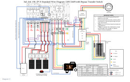
Sketched out a few possibilities since I didn't see a wiring diagram in SolArk manual that achieved the "as few changes as possible" requirement you stated.
I think I like connecting the SolArk to the 100A solar breaker the best. I know @Hedges previously mentioned a concern about overloading something, however I think this is fine.

I'm not sure what breaker size the SolArk can be configured to use. 80A breaker is enough to handle the 15K max combined output.

Bigger change. Potentially allows the PowerWall and Enphase panels to be active as long as SolArk has batteries.

I think I like connecting the SolArk to the 100A solar breaker the best. I know @Hedges previously mentioned a concern about overloading something, however I think this is fine.
- SolArk 15K max battery charge current is around 50-60A. I don't think this is required to be counted as a continuous load. It can probably also be limited.
- There are 2 disconnects (lower than 6 max from NEC)
- The solar breaker goes straight into a double lug on the meter base according to the diagram.
- You should be allowed to use load calculation instead of breakers (depends on POCO) if you have 2 separate OCPD directly attached to one meter & service. This was allowed for many years.
I'm not sure what breaker size the SolArk can be configured to use. 80A breaker is enough to handle the 15K max combined output.
Bigger change. Potentially allows the PowerWall and Enphase panels to be active as long as SolArk has batteries.
Hedges
I See Electromagnetic Fields!
- Joined
- Mar 28, 2020
- Messages
- 20,719
I think SolArk on 100A M1 breaker allows 300A total current draw, which would heat utility drop and meter contacts 2.25x the temperature rise they were designed for.
I suggest replacing main 200A breaker with 100A (which I think you show above.)
Then maximum current that can be drawn through meter (or pushed through it) is 200A.
Considering busbar for breakers has main in middle, not the end, total of main + PV breakers on that busbar should not exceed 200A.
So I'm saying M1 + M2 should be 200A or less if loads will be drawn on M1, and
M2 + PV breaker on busbar should be 200A or less.
100A M1, 100A M2, 100A PV breaker for SolArk is one possibility.
Putting GT PV and nothing else on M1 would avoid objections to not following its listing.
I don't really come up with anything greater, unless is is 100A M1 (if no loads connected, 70A if M1 has loads.) 125A M2, 70A GT PV breaker. That gives more current for loads.
The second example is likely what will be done. I was talking to someone locally about exactly that. Just trying to make sure it doesn’t void the warranty through the original install. Still considering a second battery option as wellSketched out a few possibilities since I didn't see a wiring diagram in SolArk manual that achieved the "as few changes as possible" requirement you stated.
I think I like connecting the SolArk to the 100A solar breaker the best. I know @Hedges previously mentioned a concern about overloading something, however I think this is fine.
View attachment 153208
- SolArk 15K max battery charge current is around 50-60A. I don't think this is required to be counted as a continuous load. It can probably also be limited.
- There are 2 disconnects (lower than 6 max from NEC)
- The solar breaker goes straight into a double lug on the meter base according to the diagram.
- You should be allowed to use load calculation instead of breakers (depends on POCO) if you have 2 separate OCPD directly attached to one meter & service. This was allowed for many years.
I'm not sure what breaker size the SolArk can be configured to use. 80A breaker is enough to handle the 15K max combined output.
View attachment 153206
Bigger change. Potentially allows the PowerWall and Enphase panels to be active as long as SolArk has batteries.
View attachment 153207
zanydroid
Solar Wizard
I don’t have the reference right now but I checked a few days ago to see if 120% is now allowed for center fed, and that was changed a few years ago.Considering busbar for breakers has main in middle, not the end, total of main + PV breakers on that busbar should not exceed 200A.
allows 300A total current draw, which would heat utility drop and meter contacts 2.25x the temperature rise they were designed for.
I found this on a thread for an NEC version within 2010s which is the model I was assuming above. This is the old school rule that a lot of houses in California from the 1980s, before main breakers were common and used 6 100A or smaller breakers on hotbus ( no main breaker, service conductor lugged onto bus), went in on. This is definitely less safe and potentially trickier to get approved, esp since it directly affects the POCO side protection.
230.90 Where Required.
Each ungrounded service conductor shall have overload protection.
(A) Ungrounded Conductor. Such protection shall be provided by an overcurrent device in series with each ungrounded service conductor that has a rating or setting not higher than the allowable ampacity of the conductor. A set of fuses shall be considered all the fuses required to protect all the ungrounded conductors of a circuit. Single-pole circuit breakers, grouped in accordance with 230.71(B), shall be considered as one protective device.
Exception No. 3: Two to six circuit breakers or sets of fuses shall be permitted as the overcurrent device to provide the overload protection. The sum of the ratings of the circuit breakers or fuses shall be permitted to exceed the ampacity of the service conductors, provided the calculated load does not exceed the ampacity of the service conductors.
Last edited:
Hedges
I See Electromagnetic Fields!
- Joined
- Mar 28, 2020
- Messages
- 20,719
I don’t have the reference right now but I checked a few days ago to see if 120% is now allowed for center fed, and that was changed a few years ago.
If PV backfeed was put end of longer half of busbar, and the 12 single or 6 double breakers on shorter half didn't exceed 200A, then busbar couldn't be overloaded.
If total loads didn't exceed 200A (including battery charging), the meter and utility drop wouldn't be overloaded. A house may or may not have enough loads that they could overload it if they wanted to.
zanydroid
Solar Wizard
This is where I would start my research if I ever had to work on a centerfedIf PV backfeed was put end of longer half of busbar, and the 12 single or 6 double breakers on shorter half didn't exceed 200A, then busbar couldn't be overloaded.
If total loads didn't exceed 200A (including battery charging), the meter and utility drop wouldn't be overloaded. A house may or may not have enough loads that they could overload it if they wanted to.

The Community Forum
Solar and energy storage Discussion forum, one of the most interactive and well organized forum.
www.solarsean.com
The 2017 NEC allows the 120% rule for centerfed connections, like the 2014 NEC TIA, where you can connect backfed breaker(s) at one end of the busbar, but not both. 2017 NEC 705.12(B)(2)(3)(d) A connection at either end, but not both ends, of a centerfed panelboard in dwellings shall be permitted where the sum of 125 percent of the power source(s) output circuit current and the rating of the overcurrent device protecting the busbar does not exceed 120 percent of the current rating of the busbar.
In the 2020 NEC 2020 NEC 705.12(B)(3)(4) says you can apply the 120% rule to centerfed busbars and you can backfeed breakers on both sides of the busbar, you are not limited to one side. This does not mean that you can add more inverters, it only means that you can be more balanced and if you are adding more than one inverter, you are not limited to just one end of the busbar, which makes sense. It does not let you make it the 140% rule though.
They are comparable. The EG4-18kPV is less expensive and has a a few nicer features that you may or may not be concerned with-- easier configuration, built-in remote diagnostic management, bigger wiring compartment. Personally I am likely to go for the EG4 since it has a better ability to serve all my long-term needs, but before that I was thinking SolArk 15k and before that 2xSchneider XW-Pro 6848's. The Schneider solution ultimately won't work because of wall space issues, and it costs about 2x the EG4 solution in equipment and about 3x the installation effort.assuming I am willing to spend the extra cost and not use enphase on the new portion and go to a aio inverter. would you go with solark or eg4 or something else?
EG4 is decidedly in the DIY market for now, but it looks like they are trying to get deals with the big wholesalers like CED Greentech. If you are hiring an installer that may play a role in your decision.
Similar threads
- Replies
- 4
- Views
- 225
- Replies
- 12
- Views
- 188
- Replies
- 13
- Views
- 414