diy solar

diy solar

400w System Blueprint + Alternator Charging is Now Updated

Will Prowse

Forum Owner
Staff member
Moderator
Joined
Sep 19, 2019
Messages
3,500
Location
36° N 115° W
Click here to see the blueprints in HD and full size

Thank you to @Santa for the request.

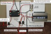
Easier to follow blueprint of the recent renogy dc dc w/ mppt system (click here for the video). There are a few ways you can wire the fusebox in, and I love tapping the inverter circuit breaker, but you don't have to. If you are pushing big loads with the fusebox, then give it a dedicated circuit breaker sized accordingly. Let me know what you guys think:

ssss.jpg
122 FGOOD.JPG
 
For those wondering about the RJ45 Jack. I asked Renogy if this new device had BT connectivity.

Question: "I Would Like To Use This Charger To Permit Charging The House Battery In My Truck Camper From The Truck's Alternator. I Would Also Plan On Adding A Battery Monitor In The Camper. I Would Also Like To Have Bluetooth Connectivity So I Can Monitor Battery State From My Truck Via My Smartphone. Is It Possible To Add The Bluetooth Module To The Monitor Or Charger?"


Response: "Thank You For Contacting Renogy, At This Point The Bluetooth Is Only Compatible With The Over Charge Controller And Not The DCDC."
 
Does not work with the bluetooth, but it will have some crazy cool functionality soon enough. I am not allowed to say much, but there will be a monitoring system that is compatible with this system. Expect release in Q4. Will probably have bluetooth. I will tell them that you want it.

An updated manual should be out next week with alternator and BVS instructions.
 
@Will Prowse

this post convinced me to go with this system, thanks! i purchased all the components clicking your links.

any update on the manual (w/alternator and BVS instructions)?
 
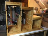
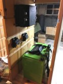
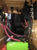
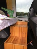
I wanted to post these pics as a thank you to Will for all his fantastic information. And maybe someone else will find it helpful too. I recently completed this alternator blueprint with a few minor variations and installed in my 2015 Sprinter campervan. The battery is a used Valence 138ah LiFePO4 from ebay (Thanks Will) and you'll notice the Renogy controller. Not shown is a 1000w pure sine inverter. The build we really straightforward and very compact. Everything fit in one section of modified Ikea cabinetry and the inverter was installed in the adjacent section. The cabinet also doubles as steps to the bed (Thanks to #vanlife youtuber BoutenkoFilms for that idea).

.IMG_2784.JPGIMG_2641.JPG
IMG_2807.JPG
IMG_2937.JPG
 
I'm going to build the 400 Watt Solar Package w/ Alternator Charging system from your blueprints for my enclosed trailer. My question is can an automatic transfer switch be wired into this system so that when parked I could plug into shore power? If so, how is it done? thank you Will
 
I am curious about his also. This looks perfect for a small van off grid power system but having the option to plug in and also charge the battery would be ideal!
 
Note, this configuration doesn't use a transfer switch. There's a separate charge controller for the shore power. So if you marry the two diagrams, the Renogy controller in Will's diagram handles the solar/alternator. A separate shore power charge controller is connected directly to the bus bars. I do like how faroutride has bus bars on both the +/- sides, but for my application that additional expense was overkill. I only provided a 4-post bus bar on the -. If you want to add more systems (ie. shore power) you may want to provide bus bars on both sides?
 
thanks Web
Note, this configuration doesn't use a transfer switch. There's a separate charge controller for the shore power. So if you marry the two diagrams, the Renogy controller in Will's diagram handles the solar/alternator. A separate shore power charge controller is connected directly to the bus bars. I do like how faroutride has bus bars on both the +/- sides, but for my application that additional expense was overkill. I only provided a 4-post bus bar on the -. If you want to add more systems (ie. shore power) you may want to provide bus bars on both sides?
I like it ! But i see it has a manual switch to change over to shore power
 
The way in read the diagram is the big grey switch (if that is what you're referring to) is between the battery and the entire positive side of the system. It's a battery disconnect switch (not a transfer switch) so you can safely work on the system or pull batteries. I don't see any transfer switches on the diagram. The discrete systems (shore, alternator, solar) isolated via their respective circuit breakers. With this diagram you could in theory be getting power from solar, alternator and shore all at once.
 
Does not work with the bluetooth, but it will have some crazy cool functionality soon enough. I am not allowed to say much, but there will be a monitoring system that is compatible with this system. Expect release in Q4. Will probably have bluetooth. I will tell them that you want it.

An updated manual should be out next week with alternator and BVS instructions.

Hey @Will Prowse -- any update on bluetooth functionality?? Thanks for everything!
 
Back
Top