mossymeadow
New Member
Hey fellow DIYers & solar enthusiasts!
I am installing an off-grid solar system for a 1400 sqft home I am currently building. The system will be installed in a metal barn, adjacent to the future home, where my wife and I currently live.
We have:
- 36 x Hyperion 400W Bifacial Solar Panel (14.4kW total)
- 3 x EG4 6000XP Off-Grid Inverter (18kW total)
- 6 x EG4-WallMount Indoor Battery (85.8 14.3kWh total)
System Details
Our panels are mounted in 6 strings of 6. The panels are 250 to 300 feet away from the barn. We will use 8 AWG copper wire to achieve a 2-3% voltage drop (depending on voltage).
Each of the 3 inverters have two MPPTS and will thus receive two strings. The string voltage should vary from 247.44V to 160.61V depending on temperature. The start up and max voltages on the inverters are 100V and 480V respectively. The PV input will be protected by a 32 AMP breaker & a 600V lightning arrestor.
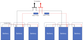
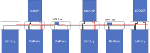
The EG4 system does not natively support 6 parallel batteries with only 3 inverters, so we are paralleling them ourselves with multiple busbars. We have chosen to use multiple busbars in order to reduce wire length (the 6 batteries span 14 feet of wall space), to reduce clutter, and to be able to use the out-of-the-box battery connectors.
We propose to accomplish this by having three batteries connect to one "sub" busbar, the other three connect to a second "sub" busbar, and then those two "sub" busbars connect to the "main" busbar. The three inverters will also connect to the "main" busbar. This design keeps all batteries in parallel. Of course, the lengths of cables are all the same size (at any given level).
The manual recommends that the busbar and wiring support 200A for each battery (so, 1200A total), but, a 1200A wire is... unrealistic (right?).
The inverters can each discharge 140A and charge 125A for a total of 420A discharge and 375A charge, respectively. However, the total discharge will be limited by a 200A main panel. Each inverter's AC output will be back-fed to a 40A breaker using 8 AWG wire.
Thus, we are inclined to ignore the 1200A recommendation. The bus bars are all rated for 600A. We are using 2/0 AWG wire from the batteries to their "sub" busbars, 4/0 AWG wire to connect the "sub" busbars to the "main" ones, and 2/0 AWG wire to connect the inverters to the "main" busbars.
Question
My main concern with this wiring would be a potential failure mode where all three of the batteries on one of the sub-panels disconnect, the sun is blazing, and all 375A of charge is pushed from the inverters to the "main" busbar, to the only remaining active "sub" busbar, to the other three batteries. While the 4/0 cable from the "main" busbar to the "sub" busbar would happily take 50% of the 375A inverter charge, it would likely not be too happy if all 100% of that load fell onto it.
Thus I am considering paralleling a second 4/0 cable between each of the sub and main busbars. Of course, the second 4/0 cables would be of the same length, so the two cables would share the load evenly. Thoughts?
I will be installing this with a long time (40+ year) builder who is well experienced in wiring up traditional electric systems. He has his own off grid solar system at home, but, he is also not a full time solar installer. Meanwhile, I only started learning about electricity 2 weeks ago. Thus, I would appreciate any suggestions, hints, or words of caution.
I didn't discuss ground and neutral, so please feel free to review those in my diagram.
Thank you!! We are super excited to get this up and running.
Attachments
Last edited:


