diy solar

diy solar

AIO supply side hookup with transfer switch

fromport

Solar Addict
Joined
Jul 24, 2021
Messages
1,191
Location
southern california (NW of LA)
I have been looking at the luxpower/eg4 18kPV12k inverter hookup schematics and I don't get the example with the supply side hookup;
Page 33 of the eg4 2.1 version manual:
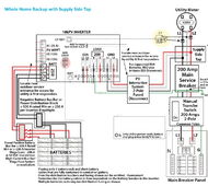
12ksupplyside.png
I erased some of the information that is imo not relevant.
The setup is currently: the manual transfer switch is set to pass by so the main breaker panel is fed by the manual transfer switch -> 200 amp main service breaker coming from the 200 amp rated meter (socket).

Because of the supply side setup, isn't it _possible_ (however unlikely) that 200 amps will be pulled from the grid from the main panel while at the same time it is possible that the AIO inverter starts to charge it's battery from the grid : 200amps @58 volts = 11,600 watts / 240 volt AC (ignoring efficiency battery charger) = 48 amps extra at 240 volt.
That with the full load of the main breaker panel, technically 248 amps could be flowing through the meter (socket) that is only rated for 200 amps.
That is 124% of nominal load, and how ever small of chance that that load is ever pulled IRL, shouldn't in this case the 200amp main breaker be de-rated to 150 amps?
Just trying to understand why this is suggested.
I hope to have an "aha" moment and say "of course, why didn't I think of that ?"
 
You have to be very careful of immediate transfer switches on AC inputs of grid interactive inverters.

Inverters locks their phasing to AC input. It can take several seconds when AC input is disconnected before pass-through relay in inverter releases from AC input. During this time, inverter AC output is present on inverter AC input terminals and the inverter will wander off phase lock.

Reapplying AC input before inverter pass-through relay releases can result in misaligned AC phasing that causes high surge currents. In the worse case the AC input breaker pops or the inverter immediately shuts down due to overload current. (actually, worse case is it can damage inverter)
 
Last edited:
You have to be very careful of immediate transfer switches on AC inputs of grid interactive inverters.

Inverters locks their phasing to AC input. It can take several seconds when AC input is disconnected before pass-through relay in inverter releases from AC input. During this time, inverter AC output is present on inverter AC input terminals and the inverter will wander off phase lock.

Reapplying AC input before inverter pass-through relay releases can result in misaligned AC phasing that causes high surge currents.
In this case we are not switching.
we have static situation where the power to the main panels comes from the grid, up to 200 amp based on wire & main breaker size but on top of that an extra 12kW AC can be pulled from the grid to charge the batteries of the AIO and imo that would overload the meter/meter/socket & 200 amp wires to the meter
 
Last edited:
Meter socket is not likely the problem.

The reason to do a line tap before main breaker panel is due to 120% rule on panel.

If injected through a main panel 50 amp breaker you will have up to 50 amps AC from PV on main panel backbone with up to 200 amps from grid totaling 250 amps in main panel which exceeds 240 amps for 120% rule.

I assume the missing inverter AC output connections in diagram goes to manual transfer switch. A similar situation exists when switching motor loads if inverter is not sync'd to AC grid. A motor load, like a water pump or air conditioner, will create a current surge if their AC source has a sudden phase shift when you switch from inverter not sync'd to grid to AC grid mains.

The setup will not likely pass inspection if you plan on being legal. It is not 'idiot proof' in its operation because you have to flip breakers in a controlled sequence to prevent issues.
 
Last edited:
Meter socket is not likely the problem.
Good to know.
How about the meter that says 200 amp rated.
Could be the limit of the internal shunt/CT that measures the current.

The reason to do a line tap before main breaker panel is due to 120% rule on panel.

I understand. but in that case the 20% is provided by the PV system, 100% is provided by the utility.


If injected to main panel breaker you will have up to 50 amps AC from PV on main panel backbone with up to 200 amps from grid totaling 250 amps in main panel which exceeds 240 amps for 120% rule.

I am making the case getting energy _from_ the grid to charge the empty batteries while _also_ pulling full 200 amp from the utility to the loads on the main breaker panel.
Together 248 amps will be provided by the utility through the meter, after which it will split:
200 amp -> main breaker -> main panel
+
48 amp -> AIO inverter to charge the batteries.

I assume the missing inverter AC output connections in diagram goes to manual transfer switch.

Yep, i removed it since I am making the case where the manual transfer switch is in the pass-through position.
There is no load/support from the inverter.
The inverter is grid tied and only starts to charge the battery at full capacity.

A similar situation exists when switching motor loads if inverter is not sync'd to AC grid. A motor load, like a water pump or air conditioner, will create a current surge if their AC source has a sudden phase shift when you switch from inverter not sync'd to grid to AC grid mains.
In my use case the inverter is synced to the grid. I am not talking about surges.
Talking about person with home with AC's , maybe a few EV's charging , maximizing the load on the main panel/breaker and add on top the load of the AIO inverter charging its battery from the grid overdoing the pull from the grid at 124% which imo should not be possible.
 
Back
Top