diy solar

diy solar

Anybody tried new JK BMS with inverter communication support?

Hello Guys,
With the recent dip in cell prices relative to a year ago, i am looking at purchasing 2 sets of 16 cells of the EVE LF280K. I am going the DIY route and looking at two options and hoping to get your thoughts especially on my choice either. The two options i am looking at are:
1. The Seplos Mason-48280L DIY Kit with BMS 3.0 with 2A active balancer. I like the standing design as this will fit into the space i have for the battery. I also like the PC Software UI and the BMS firmware is also updatable. My only con is the charging algorithm/software implementation which Andy from OffGrid garage has commented upon. I also don't know how good their balancing function is compared to others.
2. The JK Inverter BMS 200A with 2A active Balancer with screen and case from Luyuan. The JK has undergone a lot of fine tuning over the months as reported here and has a better charging algorithm implementation. I don't like the case which will lie flat on the ground. The App UI is also a bit dated. But overall i will take functionality over eye candy.
So, currently in March 2024, which amongst these two BMS do we think are a better recommendation based your own experiences using any of these two. Thank you.
 
I setup the system with the EEL box & JK 200A inverter bms on the weekend (parents off-grid system). Its running with a victron MP2, a cerbo GX, and two charge controllers with around 6kw PV. The JK is the main battery monitor / controlling the charging via DVCC on the cerbo.
All going well, but I noticed a few little niggles after a few days of running.

Battery capacity / AH remaining is not sent to the victron. Is there a workaround for this or just something JK need to add to their protocol at some point?

Float charge - I have ABS (RCV) timer set for an hour, then float set for 6hr (RFV timer), voltages 3.45 RCV and 3.35 RFV.
After an hour of ABS it switches to float, the requested charge voltage drops to the float level. But after around another hour, it goes back to ABS voltage again, for an hour, then back to float, repeating ... SOC all the while @ 99%, with more than enough sun to cover loads (no discharge from the battery).
Its possible I just didn't set it properly, need to check next time I visit, but wondering if anyone else might have a new JK with a victron and noticed the same thing ...

cheers !
 
Has anyone else has failed 485 to PC connection? The BMS board seems fine as the BMS to Cerbo CAN works perfectly. It's just I can't update the BMS using a PC. I've watched how Andy did it, and have tried permutations of dip switch, two different 485 to USBs, and cat 5 cables. The PC with JK monitor sees there's a com port, but never can sync with the BMS.
Anyone else?
 
Grrr. So now a) the bms says two cell sensors can't have their resistance calculated, b) the BMS-cerbo CAN now won't connect, and c) the basic bms controls of chg, dischg and balance don't work! Turn discharged Off and it's still discharging! Balance On yet no balancing.

Has anyone else had any of these problems?!
 
Has anyone else has failed 485 to PC connection? The BMS board seems fine as the BMS to Cerbo CAN works perfectly. It's just I can't update the BMS using a PC. I've watched how Andy did it, and have tried permutations of dip switch, two different 485 to USBs, and cat 5 cables. The PC with JK monitor sees there's a com port, but never can sync with the BMS.
Anyone else?
I have somewhat of the same issue, in that it's the JK inverter BMS. With 4 of them in parallel I can only ever see the one (master I assume, device #0). All the DIP switch's are set as per JK's instructions. Using PC software version 2.7.0, I see all the "Device" tabs along the top, but none of them show data except the first one (#0)... JK's solution to me (via chat) is to physically move the Cat5 cable from one device to the next if I want to see the data... Really JK?!!!
 
Last edited:
When I paralleled, there was no indication either of the slave data being agglomerated in the primary, which is sort of how I was figuring it should work. I also know that the pc software has been buggy all along for other reasons as well. I've just been a little hesitant to plug the master into a "bms reader" like the schneider insight facility/home, partly because I'm not sure how to verify that the right information is getting to and being dealt with on the schneider end.
 
Grrr. So now a) the bms says two cell sensors can't have their resistance calculated, b) the BMS-cerbo CAN now won't connect, and c) the basic bms controls of chg, dischg and balance don't work! Turn discharged Off and it's still discharging! Balance On yet no balancing.

Has anyone else had any of these problems?!
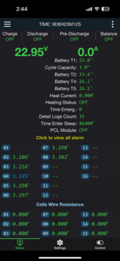
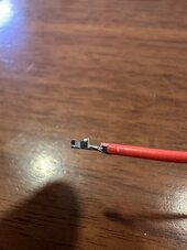
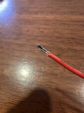
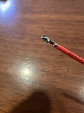
I just noticed this. The BMS isn’t reading cell one anymore. I just disassembled the entire pack and hooked it up to a different set and I still can’t get a reading on cell 1. I can read the voltages on the connector so it’s something in the BMS.
 

Attachments

  • IMG_3964.png
    IMG_3964.png
    241.8 KB · Views: 12
  • IMG_3966.jpeg
    IMG_3966.jpeg
    213.1 KB · Views: 12
  • IMG_3965.jpeg
    IMG_3965.jpeg
    307.6 KB · Views: 12
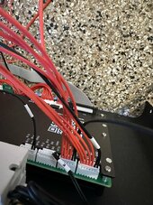
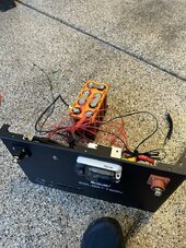
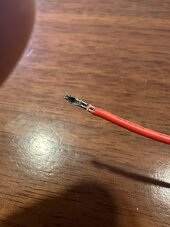
I just swapped my BMS and one getting the same thing. I wonder if the balance wire got too hot, melted and now isn’t making good contact. Im going to take apart the connector to have a look. I am running the stock balance harness as I’m running 8s and can’t use the pcb that shipped with the eel (I plan to extend those cables so I can use it).

Edit: connector looks good. Not sure what’s going on. Re-crimped the ring lug with a new ring and same issue with two BMS (same harness). I will try to get the pcb hooked up later this weekend.
 

Attachments

  • IMG_3967.jpeg
    IMG_3967.jpeg
    117.7 KB · Views: 10
  • IMG_3968.jpeg
    IMG_3968.jpeg
    86.1 KB · Views: 11
  • IMG_3970.jpeg
    IMG_3970.jpeg
    98.1 KB · Views: 10
  • IMG_3969.jpeg
    IMG_3969.jpeg
    82.3 KB · Views: 10
Last edited:
OHM out the wire and make sure it didn't break in the middle.
Okay. Sick of these stupid headway cells. Cell one is completely dead. Zero volts. Apply a charge and it takes no current. This is my third set from battery hookup. I just using them to test BMS’ so they get no use.
 
Who has version 15, firmware 11. Please look in the KAN protocol, there is item 11 (LuxPower). Thank you
There is good news and bad news:

The good:
There is now a firmware version 15.17 on the jkbms.net site:
Furthermore, there is now a new android app verison 4.19.6 on the same site.

I found that if you update the new 15.17 firmware AND use the new android app, you can now select mode 11 (luxpower) for the CAN protocol.

This firmware seems to work with both mode 2 (pylontech) and mode 6 (luxpower) on my 6000xp inverter.

Sadly that is the end of the good news, because the new firmware still suffers from the same issue with luxpower (and many other) inverters which shut off the charge controller as soon as the battery hits 100% SOC. This behavior is unchanged, so I still need to the pb-acid setting on the inverter to get it to actually charge my battery above 3.4v.

Other than that it does seem to work fine, the pack SOC, voltage, capacity, charge/discharge limit etc are all are reported just as they were using the pylontech protocol.

2 other observations:
1. The charge/discharge current limits as reported by the EG4 app are divided by 10 (actual discharge limit = 200A, reported value in eg4 app is 20A, etc). The system does actually work correctly (charge current is correctly limited to actual charge limit setpoint in BMS), so I think this is a bug in the eg4 app (maybe related to the new generator boost firmware)

2. Curiously, and perhaps worryingly, when I tried to go back to the pylontech protocol (mode 2 on both jkbms and inverter) the battery capacity reported by the inverter and the eg4 app was stuck at zero. This is worrysome, because I know that this was working in the past, so I suspect that there is some sort of logic issue. I did try the usual power cycle everything and reset the inverter settings but no luck getting the battery capacity to read on pylontech mode. I am not sure if there is some broken logic in switching protocols, or if something else about the recent updates to the inverter and bms broke it. I would be curious if anyone else can keep a close eye on the battery capacity when they make the switch and report back.
 
Has anyone managed to get these connected with Solar Assistant? I have 2 PB2A16S15P running in parallel connected to my 12kW Deye through CAN, but ideally I'd like more granular data in SA (highest / lowest / delta voltage for example). I tried with a RS485 adapter and the BMS RS485 port with different UART1 protocols in the BMS, but no combination seems to give any reasonable response. The SA site lists someone getting it to work with a Seplos BMS cable, which should be a USB RS485 adapter, unless there is something more to it?
 
The Seplos cable is just a factory made cable with a USB RS485 included, so copying it should work. As the Windows app that uses the same RS485 ports connects differently depending on whether the dip switch's are set to 1 or 0 then try both dip switch settings. Dip 1 gives access to the one battery but also access to settings and ability to update firmware, Dip 0 loses access to settings and firmware updates but access to parallel battery data.
 
Back
Top