


You are using an out of date browser. It may not display this or other websites correctly.
You should upgrade or use an alternative browser.
You should upgrade or use an alternative browser.
Anyone working with the Overkill Solar Arduino lib?
- Thread starter jbatx
- Start date

jbatx
I make stuff with things
It should work with any mqtt. Assuming you're using my code from my github repo, you just have to change the URLs and topic at the top of the code. You also need to use the fixed version of the overkill lib that's in my repo. The one linked by overkill doesn't work. If you're getting that error there's some wrong with the board or something went wrong at compile time. I think I'd try erasing the board with esptools.
Thanks. After a bit of fiddling, I got the

 github.com
library imported into ESPHome and got it working that way.
github.com
library imported into ESPHome and got it working that way.
GitHub - FurTrader/Overkill-Solar-BMS_2-Arduino-Library: Read and Write Library for Overkill Solar BMSs
Read and Write Library for Overkill Solar BMSs. Contribute to FurTrader/Overkill-Solar-BMS_2-Arduino-Library development by creating an account on GitHub.
github.com
Attachments
jbatx
I make stuff with things
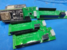
Did you make those boards?Thanks. After a bit of fiddling, I got the
library imported into ESPHome and got it working that way.GitHub - FurTrader/Overkill-Solar-BMS_2-Arduino-Library: Read and Write Library for Overkill Solar BMSs
Read and Write Library for Overkill Solar BMSs. Contribute to FurTrader/Overkill-Solar-BMS_2-Arduino-Library development by creating an account on GitHub.
...looks like Furtrader put up that new repo that's read/write on Jan 10. I haven't looked at it, don't know if the bugs in the original are fixed in the new one
Last edited:
Ya, I made the PCBs. I have a few packs I want to monitor so I didn't want to hand solder that many.
I was having an issue with the old library reading low voltage on everything. New library fixed that issue. The new library does have bug I fixed around type casting of min, but that just might be version issue. I plan open up an issue on github in a bit.
I was having an issue with the old library reading low voltage on everything. New library fixed that issue. The new library does have bug I fixed around type casting of min, but that just might be version issue. I plan open up an issue on github in a bit.
jbatx
I make stuff with things
I'd be interested in 4 of those boards. You have resistors in there that mine do not have. Could you add a display screen?
Also... I've found that lvc and hvc can sometimes cause high current (assumption) on ground coming from the bms serial port. I've had three instances where insulation melted. This time, this morning, it fried the esp and its neighboring monitor which was attached to rhe same usb hub for power.
This may [likely] be something that I'm just ignorant to... I'm not an EE, just a hack.
Turns out that the lvc issue today was a false positive on my EVE cell 240ah pack was due to terminals being loose. Presumably due to building it in 80 degree weather vs the 19 degrees we have had. Never the less, the ground surge killed the esp.
Current ones are taken, but I plan to make a few more. I don't need any displays as ESPHome feeds it to an MQTT server, and that spits it to Grafana. And the battery packs sit in a plastic tub. But I was thinking of adding some LEDs. I can add some pins for a display to the next batch if you tell me what you want and how it connects.
The board and ESP32 is powered off the BMS with a R-78HE5.0-0.3 DC-DC converter. So there is no USB or other power needed. The DC-DC converters are darn expansive at $6.54 each, but it does solve any ground loop issues and makes clean 5V power at 300ma even from a 72V battery.
The board and ESP32 is powered off the BMS with a R-78HE5.0-0.3 DC-DC converter. So there is no USB or other power needed. The DC-DC converters are darn expansive at $6.54 each, but it does solve any ground loop issues and makes clean 5V power at 300ma even from a 72V battery.

jbatx
I make stuff with things
That would be great. Which esp32 dev board are you using?
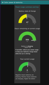
I have a firmware version that uses Blynk and a nodered app to roll up data into single values. That's been great for a quick glance at the over all situation. It's made for visitors that know nothing about solar or offgrid. ...so they don't do dumb stuff and run out of power at 4am, etc.
The "tip" changes based on the SOC and current flow.
Attachments
jbatx
I make stuff with things
forgot to ask, where/how did you make the boards? They look great.Thanks. After a bit of fiddling, I got the
library imported into ESPHome and got it working that way.GitHub - FurTrader/Overkill-Solar-BMS_2-Arduino-Library: Read and Write Library for Overkill Solar BMSs
Read and Write Library for Overkill Solar BMSs. Contribute to FurTrader/Overkill-Solar-BMS_2-Arduino-Library development by creating an account on GitHub.
Nice Grafana graphs. I like the hours remaining.
This PCB was a "lets bang it out quick because there will always be a revision 2" style prototype. So my picks of components was based on what I could get designed and made quickly in EasyEDA/JLPCB. There seems to be two types of ESP32 dev boards with one being a pin wider then the other. I picked the ESP32-DEVKITC-32D purely because EasyEDA had the right footprint to it, and I can get it from Digikey along with my other parts.
I can send you the EasyEDA project for the current version and you can just order it. I designed it to use the SMT parts they stock, so I had them to the SMT assembly. It cost about $35 bucks for 5 PCBs with assembly. I got the connector, DC-DC converter, and pin headers on Digikey and soldered them on by hand.

jbatx
I make stuff with things
skillz
Will you send me the EasyEDA project?
Last edited:
skillz
Will you send me the EasyEDA project?
I just ordered the above. Let me get them in (about 2 weeks) and check for errors before sharing.

jbatx
I make stuff with things
Yep, four. I'd like to play with the project, can you share it?They look good. No errors. Let me know if you want any.
View attachment 86236
Send me a PM.Yep, four. I'd like to play with the project, can you share it?
There is a new library available (https://github.com/FurTrader/Overkill-Solar-BMS_2-Arduino-Library) that fixes some of the reported issues like the swapping of the "length" and "data" parameters in the file bms2.cpp and the function calls to "write". Unfortunately, there is still a bug with controlling the charge and discharge FETs. First of all, the name of the function call has been changed from "OverkillSolarBms::set_mosfet_control" to "OverkillSolarBms2::set_0xE1_mosfet_control", which isn't a bug but must be changed in your sketch if you're updating to the new library. With regards to the bug for controlling the FETs in the new library, I think I've found a fix and its reported here (https://github.com/FurTrader/Overkill-Solar-BMS_2-Arduino-Library/issues/2).
Here are the lines in my sketch that I changed in order to use the new library:
#include <bms2.h> // changed from bms.h to bms2.h
OverkillSolarBms2 bms = OverkillSolarBms2(); // Instantiate version 2
bms.main_task(true); // Set new bool parameter to true so main task queries BMS
bms.set_0xE1_mosfet_control(EnableChargeFET, EnableDischargeFET); // Call new function name
jbatx
I make stuff with things
Could this monitoring solution be also used with logic to trigger is a breaker to disconnect solar input to charge controller?
i.e. just before the charge fet opens, solar input breaker opens?
Ditto for over voltage situation being discussed in other thread?
i.e. just before the charge fet opens, solar input breaker opens?
Ditto for over voltage situation being discussed in other thread?
Similar threads
- Replies
- 3
- Views
- 592
- Replies
- 15
- Views
- 1K
- Replies
- 4
- Views
- 213
- Replies
- 1
- Views
- 244