wheisenburg
Independent Solar Consultant
Back Ground
I have an Enphase system with 35*350 watt panels. It uses the IQ8+ micro inverters at 295 watts each. So the total possible output is 10,325 watts. The actual maximum output is about 9000 watts. I have 7 panels that face east and 28 that face west. The slope of my roof is about 40 degrees so I will never have both set of panels producing the maximum amount of power at the same time.
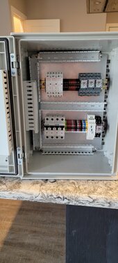
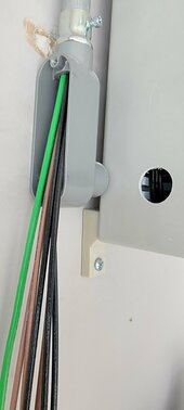
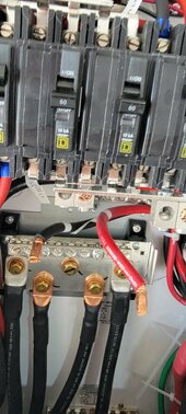
I added emergency backup capability to this system. It consists of 2 Schneider XW Pros, a PDP panel, and 3 Orient Power 5 KWH batteries. I had a main breaker installed just after the meter and before the "Main Loads Panel" at the time the Enphase system was installed. This allows me to disconnect the entire system so it can be safely worked on. I reconfigured the power flow through the system after the main breaker by adding a "Grid Panel". Currently, there are no loads installed in the Grid Panel. I do have surge protectors installed. This Grid Panel then passes through to the PDP panel. The PDP panel and the two large wiring conduits under the inverters serve as a central connection point between the incoming and out going AC, the inverters, and the batteries. The PDP panel contains circuit breakers and bus bars where everything can be wired together in one place. From there the power flows back to the Main Loads Panel. All the panel to panel wiring is 2/0 copper and is enclosed in 6 inch wire gutters.
The Schneider inverters are low frequency inverters. They have tremendous surge capability. They can put out a combined 24,000 watts. That's 480 DC amps. I am planning to eventually add 3 more batteries to my system, but right now the batteries are limited to about 300 amps. The DC system consists of dual 4/0 cables that connect to 600 amp bus bars. The individual batteries are wired with 2 #4 cables from the bus bars to the batter terminals. I ran the second cable mainly to be able to cover up the second set of terminals on the battery. Immediately after the positive DC bus each cable is routed through a class T fuse. There are 250 amp DC circuit breakers for each inverter and 100 amp circuit breakers for each battery. I was doing some load testing prior to installing the Easy Start on my A/C unit and the batteries faulted before the inverters as would be expected.
While these AC coupled systems work very well when they are connected to the grid, they are not really the best solution for Off Grid or Emergency Back up operation. A typical DC coupled system has the panels connected to charge controllers. Once the batteries are full, the charge controllers are designed to ramp down and only produce as much current as is needed to supply the current load. Micro inverters as well as other types of grid coupled inverters are designed to pump the maximum amount of power back into the grid. When these AC coupled PV inverters are running full blast that power has to go somewhere when you are off grid. So the inverter will direct that power into the batteries. Once the batteries start to become full, the inverter can raise its frequency which will cause the Grid Tied PV Inverters to ramp down their production.
This all sounds good. The problem occurs when a large load like a dryer, oven or AC system suddenly stops. It takes time to ramp down the production from the PV inverters. During that time the power will need to be pushed into the batteries. If the batteries are nearly full you could get voltage spikes in the system. Sol Ark and EG4 get around this by connecting the AC coupled Solar to the Generator input. This input has a relay that can be used to disconnect the PV when operating at a high SOC. Because of these issues manufactures make recommendations to limit the ratio of PV to inverter power, and PV to battery capacity. In some cases they even suggest that the maximum AC coupled PV be less than the DC coupled PV.
I have an Enphase system with 35*350 watt panels. It uses the IQ8+ micro inverters at 295 watts each. So the total possible output is 10,325 watts. The actual maximum output is about 9000 watts. I have 7 panels that face east and 28 that face west. The slope of my roof is about 40 degrees so I will never have both set of panels producing the maximum amount of power at the same time.
I added emergency backup capability to this system. It consists of 2 Schneider XW Pros, a PDP panel, and 3 Orient Power 5 KWH batteries. I had a main breaker installed just after the meter and before the "Main Loads Panel" at the time the Enphase system was installed. This allows me to disconnect the entire system so it can be safely worked on. I reconfigured the power flow through the system after the main breaker by adding a "Grid Panel". Currently, there are no loads installed in the Grid Panel. I do have surge protectors installed. This Grid Panel then passes through to the PDP panel. The PDP panel and the two large wiring conduits under the inverters serve as a central connection point between the incoming and out going AC, the inverters, and the batteries. The PDP panel contains circuit breakers and bus bars where everything can be wired together in one place. From there the power flows back to the Main Loads Panel. All the panel to panel wiring is 2/0 copper and is enclosed in 6 inch wire gutters.
The Schneider inverters are low frequency inverters. They have tremendous surge capability. They can put out a combined 24,000 watts. That's 480 DC amps. I am planning to eventually add 3 more batteries to my system, but right now the batteries are limited to about 300 amps. The DC system consists of dual 4/0 cables that connect to 600 amp bus bars. The individual batteries are wired with 2 #4 cables from the bus bars to the batter terminals. I ran the second cable mainly to be able to cover up the second set of terminals on the battery. Immediately after the positive DC bus each cable is routed through a class T fuse. There are 250 amp DC circuit breakers for each inverter and 100 amp circuit breakers for each battery. I was doing some load testing prior to installing the Easy Start on my A/C unit and the batteries faulted before the inverters as would be expected.
While these AC coupled systems work very well when they are connected to the grid, they are not really the best solution for Off Grid or Emergency Back up operation. A typical DC coupled system has the panels connected to charge controllers. Once the batteries are full, the charge controllers are designed to ramp down and only produce as much current as is needed to supply the current load. Micro inverters as well as other types of grid coupled inverters are designed to pump the maximum amount of power back into the grid. When these AC coupled PV inverters are running full blast that power has to go somewhere when you are off grid. So the inverter will direct that power into the batteries. Once the batteries start to become full, the inverter can raise its frequency which will cause the Grid Tied PV Inverters to ramp down their production.
This all sounds good. The problem occurs when a large load like a dryer, oven or AC system suddenly stops. It takes time to ramp down the production from the PV inverters. During that time the power will need to be pushed into the batteries. If the batteries are nearly full you could get voltage spikes in the system. Sol Ark and EG4 get around this by connecting the AC coupled Solar to the Generator input. This input has a relay that can be used to disconnect the PV when operating at a high SOC. Because of these issues manufactures make recommendations to limit the ratio of PV to inverter power, and PV to battery capacity. In some cases they even suggest that the maximum AC coupled PV be less than the DC coupled PV.
Last edited: