diy solar

diy solar

Building the sickest ® VAWT ever. Brilliant minds unite please!!

Your alternator? There is no neutral. You just have 3 windings.
It would apply to 3-phase 4 wire (plus ground) from a generator or the grid.

Well, are your windings delta or wye? If wye, there is a neutral. Don't connect load to that or reference that. Only use rectifier (+) and (-). Whether delta or wye.
 
nah not delta . star. it is not the voltage levels I am worried about being able to get at. It is the amps that should be wicked(TM). Thus with my limited knowledge I arrive at a star configuration.

But left or right. It is easy enough to try both and then see in practice how car lights actually explode!!
I will tell you this my friends.

That I do not care if I did it wrong as I am still open to learn how to do it better.

Yet when in a star configuration things just are smoother when eventually hooked up to a battery cell.

Yes, In my experience, which is crap yes I admit, Delta does not make sense to me yet.
 
The circuit diagram shown for the rectifier implies a Y configuration since it only shows one wire per phase. Tie the other ends of the coils together, but do not connect that to the - pin or anything else.
 
The circuit diagram shown for the rectifier implies a Y configuration since it only shows one wire per phase. Tie the other ends of the coils together, but do not connect that to the - pin or anything else.
yes thank you Gary. But it is already configured like that.

I will do some research where I am derailing, if at all. perhaps everything is how it is supposed to be and I have to radically rethink the coils.
 
ouch!!

Everything is as it is supposed to be.

But it seems I am aiming wayyyy to low to reach a vDC of 52 after rectification.

I looks I should be aiming vor 109 vAC(pp) per phase. Which will require a drastic rethinking of how I intend to increase the RPM of the PMA.


Here I am trusting my AI buddy again with some relevant talks;
Me:
if I want to reach a vDC of 52. What should the vAC(pp) per phase before rectification be?

-----

To calculate the required peak-to-peak AC voltage per phase (before rectification) needed to achieve a DC output voltage of 52 V, let's work backward using the relationships we've discussed.

Calculation Steps​

  1. Target DC Voltage:
    • Let VDC=52 VVDC=52 V.
  2. Formula for DC Voltage after Rectification:
    • For a 3-phase rectifier, the approximate DC voltage is given by:VDC≈VL(RMS)×1.35VDC≈VL(RMS)×1.35.
    • Rearrange to solve for VL(RMS)VL(RMS):VL(RMS)=VDC1.35≈521.35≈38.52 VVL(RMS)=1.35VDC≈1.3552≈38.52 V.
  3. Relating RMS to Peak-to-Peak Voltage:
    • RMS voltage of a sinusoidal wave is related to the peak voltage as:VL(RMS)=Vpeak2VL(RMS)=2
  • Vpeak.
  • Solve for the peak voltage:Vpeak=VL(RMS)×2≈38.52×2≈54.47 VVpeak=VL(RMS)×2
≈38.52×2
    • ≈54.47 V.
    • Peak-to-peak voltage is twice the peak voltage:Vpp=2×Vpeak≈2×54.47≈108.94 VVpp=2×Vpeak≈2×54.47≈108.94 V.

Conclusion​

To achieve a DC output voltage of 52 V after rectification using a 3-phase bridge rectifier, the required peak-to-peak AC voltage per phase (before rectification) should be approximately 109 V.
 
I think the answer is closer to 30V.

If this was 3 coils wired Delta, then 52V per coil would put out 52V peak from full-wave rectifier.
With 3 coils wired Wye, then 30V per coil would put out 52V peak.

Depending on how much current drawn, and how big a filter capacitor, need higher voltage from coil so DC voltage doesn't sag lower.
Perhaps RMS vs. peak is about right.

I think your AI assistant was thinking of single phase. Not split phase and not 3-phase. Well, at least it does mention 3-phase. But probably 3-phase Delta not Wye.
 
I have an update that will make things look hopeful again.

So all this time I should have been focusing on vAC(rms) and not vAC(pp). Now I can better design the coils to end up with the voltage I need at a specific frequency of field reversal.

I have to increase the rotational speed of the PMA. There is no way around it. There is just not eneough energy available in a slow moving disk to extract any meaningful power out of.

I am going to aim for a Hz of 40.7 as I will have to redesign the whole setup if I want a rotation increase of the PMA as opposed to the turbine of more then the 10 times I am aiming for now.

My oscope cannot measure aboth AC and DC at the same time. Readings go all over the place if I do and I nearly burn (with smoke) through the probe measuring the DC.

Also my oscope can only measure either the + or the minus of the DC at a time. So all this time I was only seeing halve wave rectification while in fact all rectifiers I have are full wave.

I make use of a shunt now to measure the voltage/amps/watts going into the battery. Far better results now then with this multi-meter in between.

With only a single 50-100-50 coil @ 0.7mm wire I get uplifting results. Amps and wattages farrr better than I have yet seen.
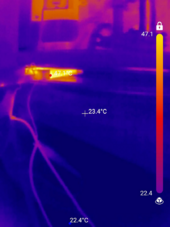
1715760055211.png

Coil stable at 47.1C. when running double frequency. When running at the intended frequency that would be 36.7C.
So those coils do not overheat rather quickly and there is quite some more power capacity in them left indeed.

But the amps wand wattage was not that stellar even though nothing to sneeze at.

So I also tried a 5-(13*10)-5 at 1.5mm wire coil in a 3 phase setting at double frequency.
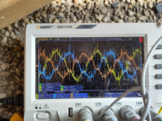
1715760176085.png


I know the waveform looks funky but that is what you get with a prototype PMA that is not sturdy and thus vibrating.
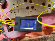

1715760313912.png

I like what I am seeing there. 39.7 watts at 11.2 amps.

I am starting to believe this is going to work out if I can just get this 10 x rotation speed to work.
 
I have to increase the rotational speed of the PMA. There is no way around it
Actually I can think of 2 ways on how to make a direct drive ( no PMA rotation increase) plausible again.

Increase the PMA diameter by a lot so that the angular velocity increases and that must surly be in some way expressible as inertial/kinetic energy. Make it large enough (like a 100 meter radius) and then even 1 RPM will translate into insane power.

Make use of core enhanced coils to increase the attraction between the electromagnets and the magnets and thus harvesting more energy from the torque of the turbine while it overcomes the electromagnetical resistance of the PMA to rotate.

Or a combination of both.

For now I will not entertain any of those options as going larger is unweildy with my current skill set and going core enhanced is unweildy with my current skill set :) :(

And lets not forget that if the PMA ends up being too powerful for it's intended operation range which is anything from 3m/s till maybe 9m/s maximum. Then it might never get up to speed as the PMA then slows the turbine down too much acting like a break even though the coils are not shorted..

You see we theoretically only have available 0.2421KW in the wind at 3m/s using a 6m diam VAWT with 2.44m tall blades according to
So I will need to keep that into account as well.

If that turn out to be correct as I have always felt that it is just too ambiguous!
 
Last edited:
let us quit the long winding. I have had enough of analysis paralysis. Famous words a good soul threw at me a while back and you know what? She was right all along.
Good thing I did admit to that the instant she said it though.

Hence forth no more measurements until the whole system is hooked up and spinning.

Lets get practical.
Please see stage 1 of a few to come to hook up the (proof of concept) PMA to the (proof of concept) turbine.

1715874522864.png
 
Last edited:
i can already tell that even this PU T10 32mm timing belt is not going to last long under the stresses it will be put under. Even if I shield it from rain and UV (and what have we) influences.
 
I still believe it.

If things will work out then we should think about a longer central column and then digging that into the ground.
Perhaps then no more need for guy wires.

Or having pontoons with a few guy wires floating on water. But then like not 1 but like how many can fit without disturbing each other in terms of wind flow.
 
Gang, I am still open to contemplating something more potent than a 1:11 ratio increase.

A 1:30 should still not destroy the PMA.

Please believe me I have been looking at it on how to do it.

I tried sprokets
I tried T5 timing belts. And of course I also tried T2.5. What are you taking me for? :)

Left or right I run into a wall.

My question thus is. How can we get this turbine / PMA connection in such a way that it is both stable and 1:30 ratio?
 
hahah yeah I know gang!!

That is a challenge indeed.

Yet finally I have gotten the 1:11 seeming stable.

This is going to be great!..

And for things to become sick we need to find to a way to accelerate beyond the 1:11.

I respect that it is not easy else I would already have done it. This is a request to the readers!!! how to do it?t.
 
Back
Top